


34
FSC Safety Manager Installation Guide
10/01
2.6
System Power Connections
Cabinet power
connections
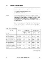
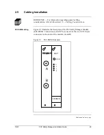
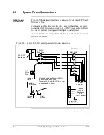
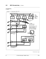
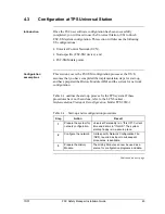
Figure 2-5 illustrates a typical power connection layout for an FSC Safety
Manager cabinet.
Conductors and breakers, used to supply power to the cabinet, are sized
using rules in the
Integration Guidelines for FSC System Cabinets
. Refer
to your site planning drawings and this figure to install power.
A cabinet will have a terminal bar at the bottom of the cabinet to connect
two or more feeders.
Figure 2-5 – Typical FSC-SM cabinet power and ground connections
150 kA MOV
Suppressor
Building
Frame
120/240 V
Entry Panel
FSC-SM Cabinet
Lightning
Ground
Safety
Ground
Lightning
Air Terminal
Safety GND
Distribution Rail
To Power
Supply Units
All ground cables are 25 mm² (AWG 4)
when not enclosed by conduit.
They must be 2.5 mm² (AWG 14) or larger
when enclosed by conduit.
Cold
Water
Pipe
Main Switch
Ground
Wires to
Backplanes
and
Comm. Equipm.
H
G
N
H
N
G
Continued on next page
Summary of Contents for FSC-SM
Page 2: ... ...
Page 6: ...iv FSC Safety Manager Installation Guide 10 01 ...
Page 12: ...x FSC Safety Manager Installation Guide 10 01 ...
Page 32: ...20 FSC Safety Manager Installation Guide 10 01 Left blank intentionally ...
Page 54: ...42 FSC Safety Manager Installation Guide 10 01 Left blank intentionally ...
Page 70: ...58 FSC Safety Manager Installation Guide 10 01 Left blank intentionally ...
Page 74: ... ...
Page 75: ... ...