


30
FSC Safety Manager Installation Guide
10/01
2.5
Cabling Installation,
Continued
FSC-SMM cabling,
continued
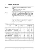
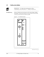
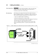
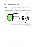
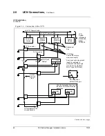
Figure 2-2 illustrates the UCN cabling required of a redundant FSC Safety
Manager system.
In this case two FSC-SMM modules are installed, one in each Central
Part. RG-6 UCN drop cables are run from the drop ports on UCN A to
UCN A F-style connectors of each FSC-SMM. RG-6 UCN drop cables are
also run from the drop ports on UCN B to UCN B F-style connectors of
each FSC-SMM.
For detailed information on cabling requirements, refer to the
Integration Guidelines for FSC System Cabinets
.
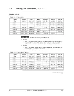
Figure 2-2 – Redundant FSC-SM UCN cabling
NIM
A
B
UCN A RG-11
UCN B RG-11
RG-6
Drop Cables
A
B
A
B
Honeywell
B
A
A
B
A
B
CP 1
CP 2
CAUTION
Remove the UCN cable from the FSC-SMM port without breaking UCN
Cable continuity, or communication will be lost to other UCN devices.
Make sure the torque specification will be 12 - 15 inch pounds to comply to UCN
connector specifications.
Continued on next page
Summary of Contents for FSC-SM
Page 2: ... ...
Page 6: ...iv FSC Safety Manager Installation Guide 10 01 ...
Page 12: ...x FSC Safety Manager Installation Guide 10 01 ...
Page 32: ...20 FSC Safety Manager Installation Guide 10 01 Left blank intentionally ...
Page 54: ...42 FSC Safety Manager Installation Guide 10 01 Left blank intentionally ...
Page 70: ...58 FSC Safety Manager Installation Guide 10 01 Left blank intentionally ...
Page 74: ... ...
Page 75: ... ...