Loops
Loop Setup
148
900 Control Station User Guide
Revision 9
May 2014
Loop Setup
Overview
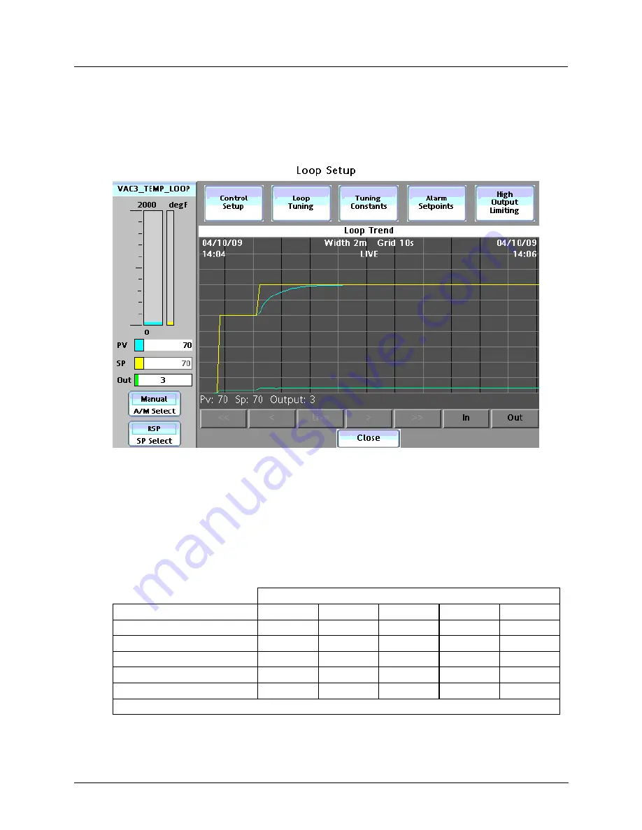
All the loop widgets let you jump to the Loop Setup display. See example below.
Above is an example of the PID Loop Setup display. At left is the loop widget, with operable buttons and
parameters.
At bottom is a loop trend. The points on the trend typically correspond to PV, SP and Output, whose pen
colors match the values on the left (aqua, yellow, green). Additional points of different colors may be
visible, depending on configuration. Use the gray buttons at the bottom to navigate and zoom.
At the top are buttons that take you to detailed popups for various loop parameters. Buttons are accessible
depending on the loop type, shown below.
Loop type
Button
PID
ON/OFF
3 POS
CARBON
A/M BIAS
Control Setup (p. 150)
X
X
X
X
X
Loop Tuning (p. 151)
X
X
X
Tuning Constants (p. 155
X
X
X
Alarm Setpoints (p. 156)
X
X
X
X
X
High Output Limiting (p. 157)
X
X
X indicates button is accessible


