


Appendix
BC-200 Manual
– P/N DOC-01-013
99
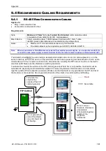
EAST WING
SOUTH
CORRIDOR
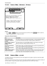
* Pt 12 Msg 1 of 1
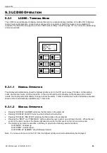
9.3.2.3
E
VENT
S
OUNDER
Switch 1 of DIP switch SW1 will enable the buzzer for alarms.
Switch 2 of DIP switch SW1 will enable the buzzer for faults.
Switch 7 of DIP switch SW1 will enable the RS232 port on the LCD80 for programming.
(Note: Activation of this switch prevents the LCD80 from communicating with the FIP.)
Switch 8 of DIP switch SW1 will select terminal mode (OFF) or annunciator mode (ON)
If the buzzer is enabled, pressing the “MUTE” button will silence the buzzer until a new event is received.
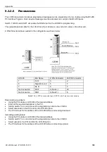
9.3.2.4
D
ISPLAY
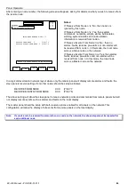
The LCD Display is made up of 4 lines of 20 characters each. Events are displayed as:
In the above example, the FIP has activated Point 6 on the LCD80. It is the first of 5 points which are active. The
Comms Indicator “Spins” when messages are being received by the LCD80.
In this example: The FIP has activated Point 12 on the LCD80.
It is the only point active.
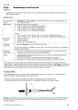
9.3.2.5
S
PECIAL
M
ESSAGES
NO ACTIVE POINTS
There are no active points on the panel programmed to
display on the LCD-80.
COMMS FAILURE
This messages flashes: The LCD80 has not been polled by
the CPU in over 10 seconds
EAST WING
NORTH
CORRIDOR
* Pt 6 Msg 1 of 5
Total Messages
Line 1
Line 2
Line 3
Comms Indicator
Message
Number
Point
Number
Summary of Contents for BC-200
Page 1: ...BC 200 OPERATION INSTALLATION PROGRAMMING MANUAL P N DOC 01 013 ECN11 0058 23 Aug 12 Rev 5 07 ...
Page 138: ...Appendix BC 200 Manual P N DOC 01 013 138 9 12 PANEL EXPANSION RELAYS ...
Page 142: ...Appendix BC 200 Manual P N DOC 01 013 142 9 9 1 13 3 4 4 R RE EL LA AY Y M MO OD DU UL LE E ...
Page 144: ...Appendix BC 200 Manual P N DOC 01 013 144 9 9 1 13 3 6 6 Z ZO ON NE E M MO OD DU UL LE E ...
Page 155: ......