


Appendix
BC-200 Manual
– P/N DOC-01-013
136
9
9
.
.
1
1
1
1
.
.
6
6
L
L
D
D
M
M
-
-
R
R
3
3
2
2
(
(
3
3
2
2
E
E
X
X
P
P
A
A
N
N
S
S
I
I
O
O
N
N
R
R
E
E
L
L
A
A
Y
Y
S
S
)
)
TB1
TB2
TB3
TB4
TB5
TB6
J5
J6
J7
J8
J10
N.O. contacts
N.O. contacts
N.O. contacts
N.O. contacts
Common for TB4
Common for TB3
Common for TB1
Common for TB2
K1
K32
K17
K18
K16
K15
K14
K13
K19
K20
K3
K4
K5
K6
K7
K31
K30
K29
K28
K27
K26
K8
K9
K12 K21
K22
K23
K24
K25
K10
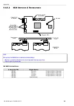
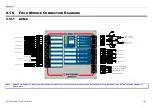
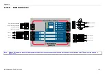
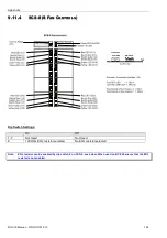
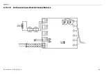
Connections:
J5, J6, J7 and J8 on the LDM-R32 connect to J5, J6, J7 and J8 on the LDM-32 respectively
J10 on the LDM-R32 connects to J10 (Relay Exp) on LDM-32
Relay contacts are on Terminal Blocks TB1 – TB6 as shown in the diagram above
Example addressing:
If annunciator address is 50, then relay K1 point address will be 1.150.O1 and relay K32 point address will be
1.150.O32
Notes: Relay contacts are rated at 1 Amp
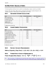
Summary of Contents for BC-200
Page 1: ...BC 200 OPERATION INSTALLATION PROGRAMMING MANUAL P N DOC 01 013 ECN11 0058 23 Aug 12 Rev 5 07 ...
Page 138: ...Appendix BC 200 Manual P N DOC 01 013 138 9 12 PANEL EXPANSION RELAYS ...
Page 142: ...Appendix BC 200 Manual P N DOC 01 013 142 9 9 1 13 3 4 4 R RE EL LA AY Y M MO OD DU UL LE E ...
Page 144: ...Appendix BC 200 Manual P N DOC 01 013 144 9 9 1 13 3 6 6 Z ZO ON NE E M MO OD DU UL LE E ...
Page 155: ......