


Appendix
BC-200 Manual
– P/N DOC-01-013
125
9.7.1.4
M
ODEM TO
FIP C
ABLE
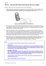
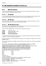
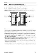
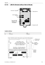
The modem is connected to the CPU debug port and uses a
special
serial cable with pin connections outlined
below:
BC-200 Debug Port
DB9(male) Labelled CONN2
Modem Connector
DB9 (male)
Modem Connector
DB25 (male)
Pin 2 RX
Pin 2
Pin 3
Pin 3 TX
Pin 3
Pin 2
Pin 5 GRND
Pin 5
Pin 7
Pin 7 RTS
Pin 4
Pin 20
Pin 7 linked to 8
Pin 4 linked to 5
Notes:
All other pins should be left disconnected.
The cable is not bi-directional. When making or connecting the cable, make sure that each end is marked
and connected correctly to either CPU or Modem.
This cable can not be used to change the AT settings of the modem. A standard modem cable (modem to
PC) should be used for setting the modem options.
9
9
.
.
7
7
.
.
2
2
P
P
R
R
I
I
N
N
T
T
E
E
R
R
/
/
P
P
A
A
G
G
E
E
R
R
/
/
H
H
L
L
I
I
I
I
N
N
T
T
E
E
R
R
F
F
A
A
C
C
E
E
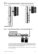
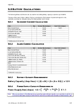
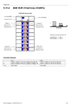
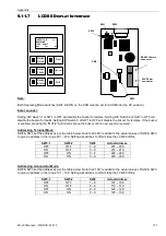
BC-200 can be interfaced to serial printers, pagers and nurse call systems using the printer port on the CPU
(CONN1). A global option on the FIP will enable/disable printing. Any standard terminal program or the BC-200
PCI history upload tool can be used to monitor the output of this port. An example of this text output is included in
the next section for reference.
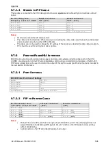
9.7.2.1
P
ORT
S
ETTINGS
BC-200 Printer Port (Conn1) Settings
Mode
RS-232
Baud Rate
9600
Data Bits
8
Stop Bits
1
Parity
Odd
Handshaking
Hardware CTS/RTS
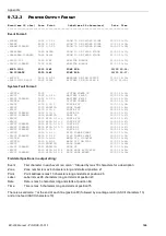
9.7.2.2
FIP
TO
P
RINTER
C
ABLE
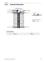
BC-200 Printer Port
(DB9 Male) Labelled CONN1
Printer Connector
(DB25)
Printer connector
(DB9)
Pin 2
(RX)
-
-
Pin 3
(TX)
Pin 3
(RX)
Pin 2
(RX)
Pin 5
(REF)
Pin 7
(REF)
Pin 5
(REF)
Pin
7
(RTS)
-
-
Pin
8
(CTS)
Pin
4
(RTS)
Pin
7
(RTS)
Notes:
Pin 8 (CTS) on the CPU side has to be high (+5v) for BC-200 to print. If the printer/pager does not
support Hardware handshaking (RTS signal), link pin 7 and 8 (on the CPU side) to allow printing
without handshaking.
A global option on the FIP will enable/disable printer output.
Summary of Contents for BC-200
Page 1: ...BC 200 OPERATION INSTALLATION PROGRAMMING MANUAL P N DOC 01 013 ECN11 0058 23 Aug 12 Rev 5 07 ...
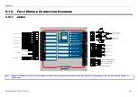
Page 138: ...Appendix BC 200 Manual P N DOC 01 013 138 9 12 PANEL EXPANSION RELAYS ...
Page 142: ...Appendix BC 200 Manual P N DOC 01 013 142 9 9 1 13 3 4 4 R RE EL LA AY Y M MO OD DU UL LE E ...
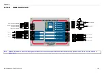
Page 144: ...Appendix BC 200 Manual P N DOC 01 013 144 9 9 1 13 3 6 6 Z ZO ON NE E M MO OD DU UL LE E ...
Page 155: ......