


Panel Operation
BC-200 Manual
– P/N DOC-01-013
71
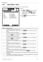
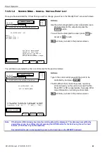
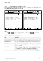
7.3.6.9
S
ERVICE
M
ENU
– T
EST
– A
LARM
/F
AULT
– AZF
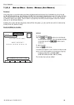
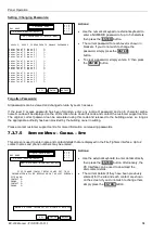
In this screen an AZF may be tested to verify its ability to detect an Alarm or Fault condition.
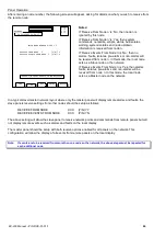
POINT STATUS:
TEST MODE IS AUTOCLEAR
SENDING ALARM TEST…GOOD RX
WAITING FOR POINT 1.2.Z3 TO ALARM
OK…CLEARING POINT
WAITING FOR POINT 1.2.Z3 TO CLEAR
OK….CLEARING ALARM/FAULT LIST
AZF TEST MENU
20 JULY 2002 14:44:37
FAULT
ALARM
ISOL
TESTING AZF POINT 1.2.Z3
BACK
USE BUTTONS TO SELECT A TEST
A = 0
F = 0
I = 0
N = 1
DAY MODE
Actions:
An
ISOL
button is provided so that the point can be
easily isolated during the test period, this button
will toggle to
DEISOL
if the point is already
isolated.
A single button press of the
ALARM
or
FAULT
buttons is all that is required to initiate the tests.
Pressing the
BACK
button will return to the previous
screen.
Note that an isolated point is seen as inactive by the
panel and hence, in a logic programming script, it
will return the value FALSE (or TRUE if the NOT
function is applied to it within the script).
All tests will require the operator to manually reset the alarm or fault after the test.
If the alarm test or fault test fails a message of
TIMEOUT ON ALARM/FAULT!!
or
TIMEOUT ON CLEAR!!
If this occurs the module should be immediately investigated for faults.
Note:
The AZF tests generate a real alarm or fault condition at the remote module, so the module itself is tested as
well as the panel to module communications.
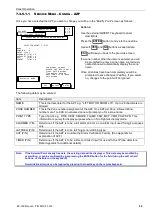
7.3.6.10 S
ERVICE
M
ENU
– T
EST
– A
LARM
/F
AULT
– A
NALOG
Will prompt the operator to enter the device address to be fault or alarm tested.
Note:
The Analog tests do not generate a real alarm or fault condition at the device. A successful test is not an
indication of the device’s ability to report a real alarm condition, its only an indication of proper
communication between the LCM and FIP.
Summary of Contents for BC-200
Page 1: ...BC 200 OPERATION INSTALLATION PROGRAMMING MANUAL P N DOC 01 013 ECN11 0058 23 Aug 12 Rev 5 07 ...
Page 138: ...Appendix BC 200 Manual P N DOC 01 013 138 9 12 PANEL EXPANSION RELAYS ...
Page 142: ...Appendix BC 200 Manual P N DOC 01 013 142 9 9 1 13 3 4 4 R RE EL LA AY Y M MO OD DU UL LE E ...
Page 144: ...Appendix BC 200 Manual P N DOC 01 013 144 9 9 1 13 3 6 6 Z ZO ON NE E M MO OD DU UL LE E ...
Page 155: ......