


Appendix
BC-200 Manual
– P/N DOC-01-013
108
9
9
.
.
5
5
.
.
5
5
F
F
A
A
U
U
L
L
T
T
C
C
O
O
D
D
E
E
S
S
These codes apply to Analog devices and are added to the history log as well as being displayed in the Fault List
when the fault occurs.
Actual Fault
Code
Displayed
Possible causes
No Response
FAULT (F01)
The device in fault is not communicating with the LCM. This fault can
occur if the device is not physically connected, damaged or set at wrong
address.
Mismatched
Hardware Type
FAULT (F02)
The actual device type is different to the programmed type. This fault
would occur if an incorrect device type is used such as a heat detector
instead of a photo optical detector.
Devices At Same
Address
FAULT (F03)
Two devices have the same address on the loop.
Incorrect Response
FAULT (F04)
The device has returned an incorrect response. This fault can occur if
the device is faulty or the loop wiring is substandard. If the resistance of
the entire loop wire exceeds 50 ohms, this fault will be observed
intermittently.
Open Circuit
FAULT (F05)
An Analog module does not have the End Of Line resistor connected or
an incorrect value of EOL is used.
Short Circuit
FAULT (F06)
There is a short circuit on the output terminals of an Analog relay
module.
Low Threshold
FAULT (F07)
A low threshold fault indicates a faulty detector which needs to be
replaced.
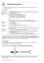
Maintenance Alert
FAULT (F08)
Analog detector needs cleaning.
Maintenance Urgent
FAULT (F09)
Analog detector needs cleaning urgently. Once the detector is in
maintenance urgent fault it will no longer provide reliable detection of
fire.
Verify Count Over 20
FAULT (F010)
Not used on BC-200.
Detector Failed Test
FAULT (F011)
LCM performs a test on each detector every 2 – 3 hours. This fault can
occur if the device is faulty or the loop wiring is substandard. If the
resistance of the entire loop wire exceeds 50 ohms, this fault will be
observed intermittently.
Security Tamper
FAULT (F012)
Not used on BC-200.
Low Temperature
FAULT (F013)
Not used on BC-200.
Ground Fault
FAULT (F014)
Less than 50kohms resistance to ground. The Ground Fault LED on the
affected LCM will be ON (refer to page 116).
Charger Fault
FAULT (F015)
Not used on BC-200.
Battery Low
FAULT (F016)
Not used on BC-200.
Battery High
FAULT (F017)
Not used on BC-200.
General Trouble
FAULT (F018)
General fault code that LCM uses when it can not detect the actual
problem with the device. This fault can occur if the device is faulty or the
loop wiring is substandard. If the resistance of the entire loop wire
exceeds 50 ohms, this fault will be observed intermittently.
Missing Address
FAULT (F019)
Not used on BC-200.
AC Fail
FAULT (F020)
Not used on BC-200.
Module External
Power Loss
FAULT (F021)
24 volt power is not connected to the Analog module. (Conventional
Zone and Control modules).
Wrong OEM Device
Type
FAULT (F022)
The device on the loop is using the wrong communication protocol.
Replace the device with a version that has compatible protocol with the
panel.
RFX Communication
Loss
FAULT (F023)
Not used on BC-200.
Summary of Contents for BC-200
Page 1: ...BC 200 OPERATION INSTALLATION PROGRAMMING MANUAL P N DOC 01 013 ECN11 0058 23 Aug 12 Rev 5 07 ...
Page 138: ...Appendix BC 200 Manual P N DOC 01 013 138 9 12 PANEL EXPANSION RELAYS ...
Page 142: ...Appendix BC 200 Manual P N DOC 01 013 142 9 9 1 13 3 4 4 R RE EL LA AY Y M MO OD DU UL LE E ...
Page 144: ...Appendix BC 200 Manual P N DOC 01 013 144 9 9 1 13 3 6 6 Z ZO ON NE E M MO OD DU UL LE E ...
Page 155: ......