


Panel Operation
BC-200 Manual
– P/N DOC-01-013
21
7
7
.
.
1
1
.
.
3
3
E
E
N
N
T
T
E
E
R
R
I
I
N
N
G
G
I
I
N
N
F
F
O
O
R
R
M
M
A
A
T
T
I
I
O
O
N
N
On screens where character information needs to be entered, such as point labels, this must be done using an
external QWERTY style keyboard plugged into the PS2 keyboard plug on the rear of the CPU panel. On screens
(e.g. menus, change time/date) that require only numbers to be entered, the ten digit numeric keypad can be
used.
7
7
.
.
1
1
.
.
4
4
S
S
Y
Y
S
S
T
T
E
E
M
M
C
C
O
O
U
U
N
N
T
T
E
E
R
R
S
S
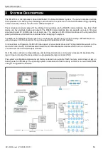
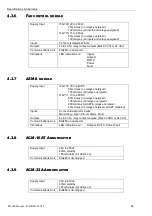
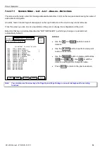
On the top right hand side of all screens are the system counters showing the total number of
alarms, faults, isolates and non-alarm (active) events on the system at any time. If a device is
both isolated and in fault it will increment both counters. For more information as to which points
are isolated, refer to the list menus.
7
7
.
.
1
1
.
.
5
5
P
P
O
O
I
I
N
N
T
T
F
F
O
O
R
R
M
M
A
A
T
T
S
S
There are three different types of point in the BC-200 system – real (or physical) points, virtual (software
generated) points and network points.
All points on the distributed ring and the Analog addressable loops are real points. Distributed points on field
modules are controlled and referred to in “R.M.IO” format. i.e.: Ring
.
Module
.
I/O – where I/O can consist of input,
output or AZF. Analog addressable points on the addressable loops are controlled and referred to in “Loop, I/O
format” i.e. Loop I/O where I/O can consist of module or detector number.
Virtual points are referred to as VPx where x can range from 1 to 1000. Virtual points are actually the output from
a script equation and are discussed later in this manual (refer to page 95).
Network points are referred to as NPx where x can range from 1 to 1000. Each network node can have up to 1000
Netpoints. Network points are real or virtual points mapped at any network node that is required to interact with
other network nodes (refer to page 92).
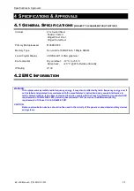
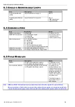
Examples are as follows.
Point to be referred to
Syntax
Ring 1, Module 1, Output 1
1.1.O1
Ring 1, Module 20, AZF input 1 (AZM-8)
1.20.Z1
Ring 1, Module 30, input 1 (FAN-C)
1.30.I1
Ring 1, Annunciator 1 (module 101), Output 1 (led #1)
1.101.O1
Ring 1, Annunciator 50 (module 150), Input 1 (button #1)
1.150.I1
Loop 1 Detector 1
L1D1
Loop 1 Module 1
L1M1
Expansion relay 1
XR1
Virtual point 1
VP1
Network point 1 on Node 1
N1.NP1
A = 2
F = 5
I = 10
N = 5
Summary of Contents for BC-200
Page 1: ...BC 200 OPERATION INSTALLATION PROGRAMMING MANUAL P N DOC 01 013 ECN11 0058 23 Aug 12 Rev 5 07 ...
Page 138: ...Appendix BC 200 Manual P N DOC 01 013 138 9 12 PANEL EXPANSION RELAYS ...
Page 142: ...Appendix BC 200 Manual P N DOC 01 013 142 9 9 1 13 3 4 4 R RE EL LA AY Y M MO OD DU UL LE E ...
Page 144: ...Appendix BC 200 Manual P N DOC 01 013 144 9 9 1 13 3 6 6 Z ZO ON NE E M MO OD DU UL LE E ...
Page 155: ......