


Specifications & Approvals
BC-200 Manual
– P/N DOC-01-013
13
4
4
.
.
3
3
.
.
2
2
T
T
E
E
R
R
M
M
I
I
N
N
A
A
T
T
I
I
O
O
N
N
B
B
O
O
A
A
R
R
D
D
(
(
F
F
I
I
M
M
)
)
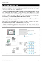
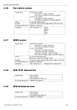
Supply Input
requirements
22 to 28V dc – fused at 9A (self-resetting)
55mA max (without CPU board or field loops connected)
210mA max (with CPU board, without field loops connected)
Alarm Inputs
Two conventional Alarm Zone inputs are provided, detecting open
circuit fault, alarm, and normal. Each input is monitored and requires a
4K7 (nom) EOL resistor.
Power
Outputs
Auxiliary Power Output 20-28V 1A max
24V dc & 5V dc Power to Ring Expander Boards
CPU power supply – 5V DC
±
5% 3A
Alarm
Outputs
4 x 1A monitored outputs (Bell & 3 spares – 4k7 EOL resistor)
4 x ELV 1A relay contact outputs (Common Alarm, Fault plus 2 spare)
Communicati
ons Link
EIA485 on dual ports
24Vdc (nom) 2A (max)
Note: Additional auxiliary power supply(s) may be required for
annunciators, depending on the number of modules installed.
Indications
LED indications of relay outputs, fuses, ring power and ground fault
4
4
.
.
3
3
.
.
3
3
P
P
A
A
N
N
E
E
L
L
E
E
X
X
P
P
A
A
N
N
S
S
I
I
O
O
N
N
R
R
E
E
L
L
A
A
Y
Y
S
S
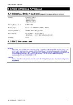
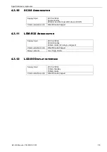
Panel Expansion Relays (XR)
IFS-717
Up to 64 x 30Vdc @ 1A non-monitored relay
contact outputs via 8 x IFS-717 relay boards
4
4
.
.
3
3
.
.
4
4
L
L
C
C
M
M
/
/
L
L
E
E
M
M
A
A
D
D
D
D
R
R
E
E
S
S
S
S
A
A
B
B
L
L
E
E
L
L
O
O
O
O
P
P
C
C
O
O
N
N
T
T
R
R
O
O
L
L
L
L
E
E
R
R
M
M
O
O
D
D
U
U
L
L
E
E
S
S
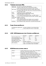
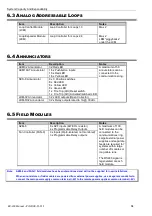
Minimum
Nominal
Maximum
Operating voltage (V dc)
20.6
24
29
Loop communications voltage
15
24
32
Loop current limit (mA)
340
400
430
LCM/LEM Pair (Q Current)
140
200
Communications Link
EIA485 on dual ports
LED Indications
Green – Heart beat / Onboard 5Vdc supply OK
Amber – Ground fault / faulty card detected
4
4
.
.
3
3
.
.
5
5
N
N
C
C
M
M
N
N
E
E
T
T
W
W
O
O
R
R
K
K
C
C
O
O
N
N
T
T
R
R
O
O
L
L
M
M
O
O
D
D
U
U
L
L
E
E
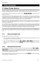
NCM-W
Supports twisted-pair wire medium, data is regenerated at
each node. 312.5K baud transmission rate.
NCM-F
Supports fibre-optic medium (62.5/125 or 50/125
micrometres – multimode). Single mode available. 312.5K
baud transmission rate. Data is regenerated at each node.
HS-NCM
High-speed data communications (12 Mb wire, 100 Mb
MF/SF fibre). Multi-mode fibre optic (MF), single-mode fibre
optic (SF),wire (W), or a combination of W/MF/SF
communications path.
Summary of Contents for BC-200
Page 1: ...BC 200 OPERATION INSTALLATION PROGRAMMING MANUAL P N DOC 01 013 ECN11 0058 23 Aug 12 Rev 5 07 ...
Page 138: ...Appendix BC 200 Manual P N DOC 01 013 138 9 12 PANEL EXPANSION RELAYS ...
Page 142: ...Appendix BC 200 Manual P N DOC 01 013 142 9 9 1 13 3 4 4 R RE EL LA AY Y M MO OD DU UL LE E ...
Page 144: ...Appendix BC 200 Manual P N DOC 01 013 144 9 9 1 13 3 6 6 Z ZO ON NE E M MO OD DU UL LE E ...
Page 155: ......