


Appendix
BC-200 Manual
– P/N DOC-01-013
111
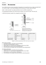
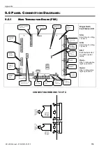
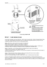
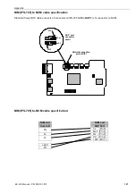
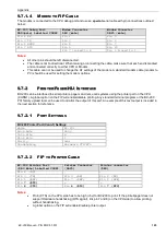
9.6.1.1
POWER SUPPLY CONNECTIONS - PS243 & PS249
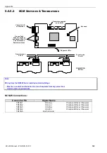
IFS-704/714/724 TERMINATION BOARD
TERM 2
B
a
tL
o
w
S
y
sF
a
il
0
V
B
T
e
st
M
F
a
il
V
B
a
tt
2
4
V
In
p
u
t
0
V
In
p
u
t
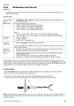
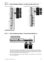
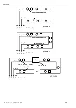
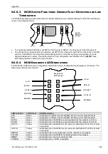
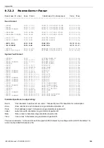
9.6.1.2
P
OWER
S
UPPLY
C
ONNECTIONS
- NPS-2/5/11
The following settings are used when connecting a NPS power supply to an IFS-724 FIM using the ribbon cable:
1.
The CPU must have V5.02 or above firmware installed.
2.
Set the bottom dipswitch on mode dipswitch U25 (on the back of the CPU) to the on position. Note that the
dipswitch can be marked 1 or 4. Always set the dipswitch closest to the upload/download port.
3.
J6 on IFS-724 FIM board must be fitted.
NI-2012
Power Supply
Interface (PSI)
IFS-724 FIM
Termination Board
NI-2012 (PSI) Dipswitch Settings:
Normal operation:
All off
NZ Operation:
1 on, all others off
Manual mode:
2 on, all others off
Fit Link at J6
Refer to Power
Supply Interface
(PSI) Manual for
more information
Summary of Contents for BC-200
Page 1: ...BC 200 OPERATION INSTALLATION PROGRAMMING MANUAL P N DOC 01 013 ECN11 0058 23 Aug 12 Rev 5 07 ...
Page 138: ...Appendix BC 200 Manual P N DOC 01 013 138 9 12 PANEL EXPANSION RELAYS ...
Page 142: ...Appendix BC 200 Manual P N DOC 01 013 142 9 9 1 13 3 4 4 R RE EL LA AY Y M MO OD DU UL LE E ...
Page 144: ...Appendix BC 200 Manual P N DOC 01 013 144 9 9 1 13 3 6 6 Z ZO ON NE E M MO OD DU UL LE E ...
Page 155: ......