


Panel Operation
BC-200 Manual
– P/N DOC-01-013
35
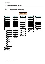
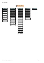
7.3.3.7.1.1
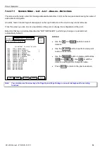
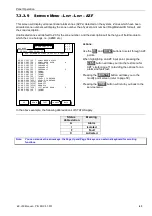
Service Menu – List – List – Analog – Detectors – Status
This screen will show a reading of the selected Analog addressable detector updated every 3 seconds, 255 times.
The detector’s current configuration is displayed together with “live readings” as shown below.
Heat Detector
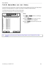
Smoke Detector
L1D2
(Z001) > APARTMENT 1 BATHROOM
Poll Mode
> FlashScan Mode
Programmed As
> HEAT
Actual Device
> HEAT
Device State
> NORMAL
Device Status
> NORMAL
LED Status
> Polling
Detector Values:
Alarm
= 0%
Peak Temperature
= 30 C
Temperature = 24 C
Day Alm Sensitivity= 5
Night Alarm Sens
= 1
Device Scanned 255 Times
.
ANALOG MENU – STATUS
A = 0
F = 0
I = 0
N = 0
20 JULY 2002 14:44:37
PREV
TEST
Menu
DAY MODE
NEXT
RESET
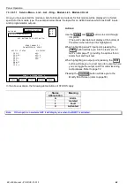
L1D3
(Z990) > APARTMENT 1 BEDROOM
Poll Mode
> FlashScan Mode
Programmed As
> PHOTO-OPTICAL
Actual Device
> PHOTO-OPTICAL
Device State
> NORMAL
Device Status
> NORMAL
LED Status
> Polling
Detector Values:
(Needs Cleaning)
Alarm
= 0%
Peak Alarm Value
= 10%
Prealarm
= 0%
Day Alm Sensitivity
= 5
Compensation = 81%
Day PreAlarm Sens
= 5
Night Alarm Sens
= 1
Night PreAlarm Sens
= 1
Device Scanned 255 Times
.
ANALOG MENU – STATUS
A = 0
F = 0
I = 0
N = 0
20 JULY 2002 14:44:37
DAY MODE
PREV
TEST
Menu
NEXT
RESET
Note:
“:Zxxx” is displayed after the descriptor, xxx is the zone number mapped to the detector. A zone number of 0
is an indication that the detector is not mapped to a zone.
Actions:
Press the
PREV
buttons to move to the previous installed point.
Press the
NEXT
buttons to move to the next installed point.
Press the
TEST
button to enter test menu for the detector.
Press the
RESET
button to re-initialise the detector.
Press
MENU
to return to the Analog Menu screen.
Explanations of terms:
Variable
Range
Description
Poll Mode
CLIP
Shows the current polling protocol being used. CLIP = 1 detector
at a time. Polling mode is auto sensed at start-up
Programmed As
8 Types
Detector type programmed into panel
Actual Device
8 Types
Detector type physically seen on loop.
Device State
Normal/Active/Alarm
Shows alarm or activated condition of point.
Device Status
23 fault types
Detailed description of fault condition. i.e.: “No Response”
LED Status
4 Types
Polling, On, Off, Polling ID
Alarm
%
Current Percentage of alarm or Degree Celsius
Pre-alarm
%
Current Percentage of Pre-alarm
Peak Alarm Value
% or
O
C
Highest reading since last reset.
Drift Compensation
%
Please refer to page 107 for information on Drift Compensation.
Sensitivities
1-9
Detector sensitivity for day/night, alarm/pre-alarm. Please refer to
page 104 for explanation information on sensitivity settings.
Summary of Contents for BC-200
Page 1: ...BC 200 OPERATION INSTALLATION PROGRAMMING MANUAL P N DOC 01 013 ECN11 0058 23 Aug 12 Rev 5 07 ...
Page 138: ...Appendix BC 200 Manual P N DOC 01 013 138 9 12 PANEL EXPANSION RELAYS ...
Page 142: ...Appendix BC 200 Manual P N DOC 01 013 142 9 9 1 13 3 4 4 R RE EL LA AY Y M MO OD DU UL LE E ...
Page 144: ...Appendix BC 200 Manual P N DOC 01 013 144 9 9 1 13 3 6 6 Z ZO ON NE E M MO OD DU UL LE E ...
Page 155: ......