


Appendix
BC-200 Manual
– P/N DOC-01-013
112
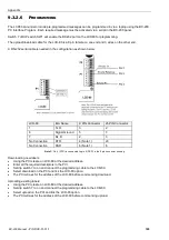
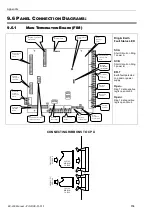
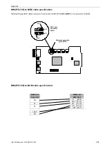
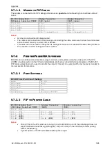
9.6.1.3
M
AIN
T
ERMINATION
B
OARD
– C
ONNECTING
RS485
+IN
-IN
SHIELD
+OUT
-OUT
SHIELD
COMMS CABLE TO FIRST MODULE
COMMS CABLE FROM LAST MODULE
-
+
-
+
TERM 4
SOCKET
PLUG
TERM 6
C
o
m
m
s
A
C
o
m
m
s
B
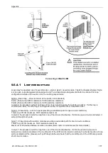
Note:
Terminate the shield at the outside of the FIP cabinet (ground). Where this is not possible, the shield must be
terminated to physical ground immediately adjacent to cable entry. Between Field modules, connect shields
together outside of their respective enclosures. Make sure that the shield is only grounded at the FIP and not
at the modules or annunciators. Do not ground both ends of the shield; one end should be left floating.
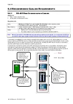
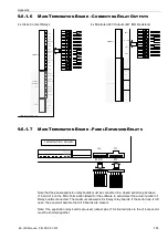
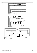
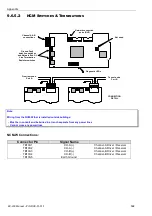
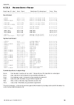
9.6.1.4
M
AIN
T
ERMINATION
B
OARD
– C
ONNECTING
24VDC
+AZ1
-AZ1
+AZ2
-AZ2
TERMINATION BOARD
PWR A(+)
PWR A(-)
PWR B(+)
PWR B(-)
TO FIRST
MODULE IN
LOOP
FROM LAST
MODULE IN
LOOP
+ 24V
- 24V
+ 24V
- 24V
PLUG
SOCKET
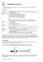
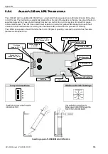
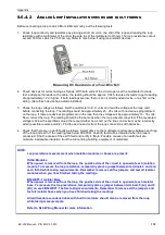
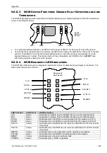
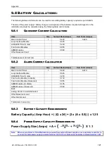
9.6.1.5
M
AIN
T
ERMINATION
B
OARD
– C
ONNECTING
AZF’
S
1 & 2
+AZ1
-AZ1
+AZ2
-AZ2
TERMINATION BOARD
ALARM ZONE INPUT
UNUSED INPUT
4700 Ohms
Summary of Contents for BC-200
Page 1: ...BC 200 OPERATION INSTALLATION PROGRAMMING MANUAL P N DOC 01 013 ECN11 0058 23 Aug 12 Rev 5 07 ...
Page 138: ...Appendix BC 200 Manual P N DOC 01 013 138 9 12 PANEL EXPANSION RELAYS ...
Page 142: ...Appendix BC 200 Manual P N DOC 01 013 142 9 9 1 13 3 4 4 R RE EL LA AY Y M MO OD DU UL LE E ...
Page 144: ...Appendix BC 200 Manual P N DOC 01 013 144 9 9 1 13 3 6 6 Z ZO ON NE E M MO OD DU UL LE E ...
Page 155: ......