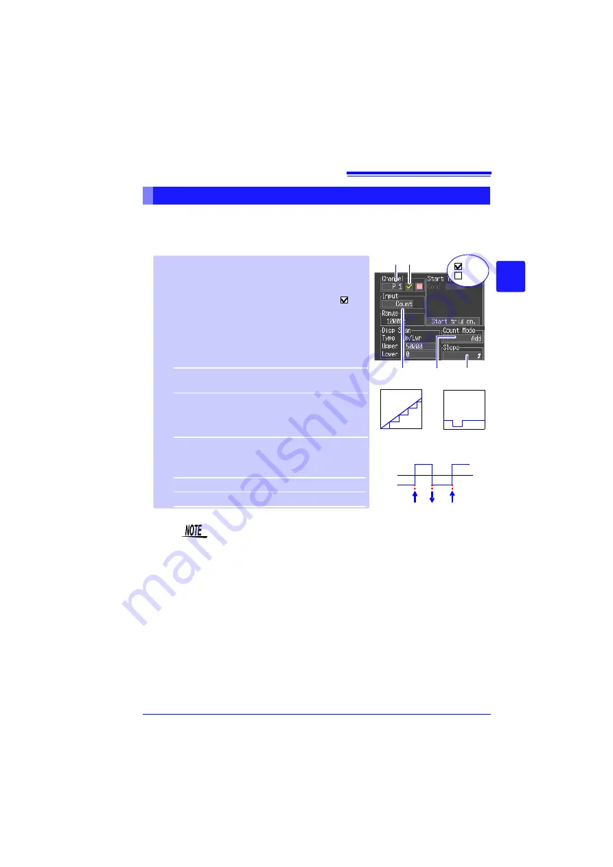
3.4 Setting Configuration 2 – Input Channel Settings
53
3
3
Chapt
er
3 Sett
ing be
fore M
easure
ment
Configure these settings for each pulse channel receiving input from a pulse
output device such as a watt-hour or flow meter.
Use the scaling function to display integrated pulse counts as the correspond-
ing physical units (such as Wh or VA) of the measurement parameter (p. 58).
Integration (Count) Measurement Settings
• When using the scaling function, the integrated pulse count can
be displayed after conversion to the measurement target’s prop-
erty (Wh, VA, etc.). (p. 58)
• The count will be saturated when the pulse count exceeds
1,073,741,823. If there is a possibility that this number may be
exceeded, it is recommended to set the integration mode to
instantaneous and tabulate the results later with Excel or a simi-
lar application.
1
Select a channel (
P 1
to
P 4
) for the
[Chan-
nel]
setting contents.
2
To enable measurement on the channel,
select On to display the check mark (
).
3
Select
[Count]
for the
[Input]
(input type)
setting.
4
Select the measurement method from the
[Count Mode]
settings.
Setting options:(
default setting)
5
Select the basis of measurement from the
[Slope]
settings.
Setting options:(
default setting)
Add
*
Counts the number of pulses acquired
from the start of measurement.
Inst
Counts the number of pulses acquired dur-
ing each recording interval. The pulse
count is reset at the beginning of each re-
cording interval.
Counts the number of L - H transitions.
Counts the number of H - L transitions.
Totalized
[Add]
Instantaneous
[Inst]
0 V
L
H
1 2
: On
: Off
3
4
5
Summary of Contents for LR8431
Page 2: ......
Page 20: ...Operating Precautions 12...
Page 44: ...2 5 Zero Adjustment 36...
Page 74: ...3 7 Viewing All Channel Settings in a List 66...
Page 88: ...4 5 About Recording Operation 80...
Page 120: ...6 6 Transferring Data to a Computer USB Drive Mode 112...
Page 126: ...7 2 Numerical Value Calculation Expressions 118...
Page 136: ...8 3 Making System Settings 128...
Page 144: ...9 5 Synchronous Measurements with Multiple Instruments 136...
Page 154: ...Chapter 10 Specifications 146...
Page 198: ...Appendix 11 Pulse Input Circuit Diagram A40...
Page 202: ...Index Index 4...
Page 203: ......


