background image

PART THREE - OPERATION

SECTION 4 - ANALYZER CONFIGURATION

Model F53 Flow Monitor/Totalizer (universal-mount 1/2 DIN)

Rev. 1-201

40

Select FLOW UNITS

(for displayed flow rate)

filter time to use is a compromise. The higher the filter time,
the longer the sensor signal response time will be to a
change in the actual process value.

1.

With the 

 screen displayed, use 

Ø

Ø

 key

 to

select the “SET FILTER” line.

2.

Press 

ENTER key

 to display a screen like

 . Use 

arrow keys

 to adjust the dis-

played value to the desired filter time, and press

ENTER key

 to enter this value.

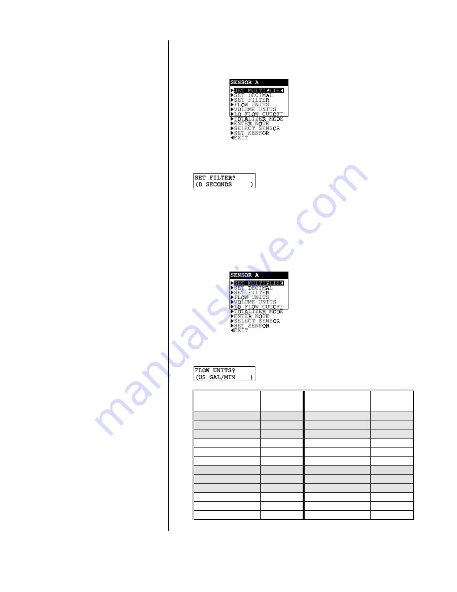
Select desired measurement units for displayed flow rate.

1.

With the 

 screen displayed, use 

Ø

Ø

 key

 to

select the “FLOW UNITS” line.

2.

Press 

ENTER key

 to display a screen like

 . Use 

Ø

Ø

 and 

×

×

 keys

 to view choices.

Flow Unit Choice

Displayed

Annunciator

Flow Unit Choice

Displayed

Annunciator

 US  GAL/MIN

GPM

 CUBIC  M/SEC

CMS

 US  GAL/HOUR

GPH

 CUBIC  M/MIN

CMM

 US  GAL/DAY

GPD

 CUBIC  M/HOUR

CMH

 MIL US GAL/DAY

MGD

 ACRE-FEET/HOUR

AFH

 LITERS/SEC

LPS

 OIL  BARREL/SEC

BBS

 LITERS/MIN

LPM

 OIL  BARREL/MIN

BBM

 LITERS/HOUR

LPH

 OIL  BARREL/HR

BBH

 LITERS/DAY

LPD

 IMP  GAL/MIN

GPM

 MIL  LITERS/DAY

MLD

 IMP  GAL/SEC

GPS

 CUBIC  FT/SEC

CFS

 IMP  GAL/HOUR

GPH

 CUBIC  FT/MIN

CFM

 MIL IMP GAL/DAY

MGD

 CUBIC  FT/HOUR

CFH

 US  GAL/SEC

GPS

Summary of Contents for F53

Page 1: ...wide Headquarters and Sales GLI International Inc 9020 West Dean Road Milwaukee Wisconsin 53224 U S A Represented By In the interest of improving and updating its equipment GLI reserves the right to alter specifications to equipment at any time A company Viridor Instrumentation Phone Fax E mail Web 414 355 3601 414 355 8346 info gliint com www gliint com ...

Page 2: ...IN Rev 1 201 2 This operating manual and other GLI operating manuals are available on GLI s web site at gliint com when viewed using Adobe s free Acrobat reader To get this reader link to Adobe through GLI s web site or visit Adobe s web site at adobe com ...

Page 3: ...ion is likely when 1 The analyzer appears visibly damaged 2 The analyzer fails to operate properly or provide the intended measurements 3 The analyzer has been stored for long periods at temperatures above 158 F 70 C This analyzer must be installed by personnel specially trained in accordance with relevant local codes and instructions contained in this operating instruction manual Observe the anal...

Page 4: ...ty period or if GLI International determines that defects or damages are due to normal wear misapplication lack of mainte nance abuse improper installation alteration or abnormal conditions GLI International s obligation under this warranty shall be limited to at its option re placement or repair of this product The product must be returned to GLI International freight prepaid for examination The ...

Page 5: ...lug Sensor B Wire Colors Connect To Sensor D Wire Colors Connect To Red Terminal 12 on TB1 Red Terminal 16 on TB1 Black Terminal 13 on TB1 Black Terminal 17 on TB1 Cable shield Grounding strip lug Cable shield Grounding strip lug B CONNECTING LINE POWER Important Follow instructions in PART TWO Section 3 5 to connect line power to the analyzer C ADJUSTING DISPLAY CONTRAST Ambient lighting conditio...

Page 6: ...G VOLUME READOUT volume unit annunciator and totalizer reset mode Unlike flow rate volume is shown only as a whole number without a multiplier Choose from a variety of volume measurement unit annunciators The totalizer is factory set for auto reset which resets the displayed volume to zero after reaching its maximum limit After automatically resetting the totalizer starts a new count Conversely th...

Page 7: ...omplete adjustment details NOTE The following configuration calibration procedure is only for Sensor A and only for GLI sensors Configure calibrate other sensors in the same way using their respective menu screens To enter specific data for non GLI sensors see PART THREE Section 4 2 sub section SET SENSOR Data under the Non GLI Sensor Setup category 1 With the screen displayed use Ø Ø key to selec...

Page 8: ...zer is now ready to meas ure Sensor A flow volume GLI Pipe Mount Sensor Setup SET PIPE ID A Determine actual inside pipe diameter Actually measure it or refer to an appropriate table NOTE Pipe IDs for commonly used Schedule 40 and Schedule 80 pipes are listed in Ta bles A and B in PART THREE Section 4 2 under the SET SENSOR Data subheading B With the SET SENSOR screen displayed use Ø Ø key to sele...

Page 9: ...ation 21 2 2 Mounting 21 23 2 3 Conduit Hole Requirements 23 SECTION 3 ELECTRICAL CONNECTIONS 3 1 Flow Sensor s 25 26 3 2 Analog Outputs 26 27 3 3 Relay Outputs 27 28 3 4 Pulsed Outputs contact closure 28 3 5 Closed Contact TTL Input 28 3 6 Line Power 29 P A R T T H R E E O P E R A T I O N SECTION 1 USER INTERFACE 1 1 Display 30 31 1 2 Keypad 31 32 1 3 MEASURE Screen normal display mode 32 33 SECT...

Page 10: ...Sensor SET SLOPE and SET OFFSET Values 47 48 4 3 Configuring CALCULATION Measurement SET VARIABLE X 49 SET VARIABLE Y 50 SET FORMULA X Y X Y X Y or X Y x 100 50 Select DISPLAY FORMAT decimal and multiplier 51 52 4 4 Configuring Analog Outputs 1 and 2 SET PARAMETER representation 53 54 SET 0 4 mA and 20 mA VALUES 54 55 SET FILTER Time 55 Select SCALE 0 mA 4 mA low endpoint 55 4 5 Configuring Relays...

Page 11: ... Timer Setup Guidelines 79 7 3 Overfeed Timer Timeout Operation 79 7 4 Resetting Overfeed Timers 79 7 5 Interactions with Other Analyzer Functions 79 80 SECTION 8 HART OPTION 8 1 Introduction 81 8 2 Analyzer Operating Modes for HART Network 82 83 8 3 SINGLE MODE Point to Point Wiring Arrangement 83 8 4 MULTI DROP Wiring Arrangement 84 8 5 HART Preferences Setup Changing Polling Address 85 Viewing ...

Page 12: ...eplacing Relays 91 SECTION 2 PRESERVING MEASUREMENT ACCURACY 2 1 Keeping Sensor s Clean 92 2 2 Avoiding Electrical Interference 92 SECTION 3 TROUBLESHOOTING 3 1 Checking Electrical Connections 92 3 2 Verifying Sensor Operation 92 3 3 Verifying Analyzer Operation 92 93 3 4 Verifying Interconnect Cable Integrity 93 SECTION 4 ANALYZER REPAIR RETURN 4 1 Customer Assistance 94 4 2 Repair Return Policy ...

Page 13: ... 90 130 VAC 29 Figure 2 7 Connecting 230 Volt Single Phase Line Power 180 260 VAC 29 Figure 2 8 Connecting 230 Volt Split Phase Line Power 180 260 VAC 29 Figure 3 1 Analyzer Keypad 31 Figure 3 2 Location of SINGLE MODE MULTI DROP Switch HART equipped analyzers only 83 Figure 3 3 HART SINGLE MODE Point to Point Wiring Arrangement for single analyzer 83 Figure 3 4 HART MULTI DROP Wiring Arrangement ...

Page 14: ...Model F53 Flow Monitor Totalizer universal mount 1 2 DIN Rev 1 201 14 ...

Page 15: ...lier 2 SENSOR B flow rate with multiplier 3 SENSOR C flow rate with multiplier 4 SENSOR D flow rate with multiplier 5 SENSOR A volume no multiplier 6 SENSOR B volume no multiplier 7 SENSOR C volume no multiplier 8 SENSOR D volume no multiplier Combined Data Readouts 1 Sensor A flow rate and volume 2 Sensor B flow rate and volume 3 Sensor C flow rate and volume 4 Sensor D flow rate and volume 5 Sen...

Page 16: ...ipe in which the sensor will be installed When using a GLI tee mounted sensor enter the tee size and tee material For a NON GLI SENSOR determine and enter appropriate SLOPE and OFFSET values The CALIBRATE menu enables you to linearly offset meas ured flow readings one of two ways by using the OFFSET BY method to enter a or offset value SET TO method to enter a known measured value See PART THREE S...

Page 17: ...rm relay that automatically energizes when the WARNING CHECK STATUS message flashes on the MEASURE screen This occurs when the analyzer detects a fail diagnostic condition See PART THREE Section 6 1 for more details For relay setup details refer to PART THREE Section 4 5 The analyzer provides two SPDT pulsed contact closure outputs A and B for remote use such as counting or pumping Each pulsed out...

Page 18: ...zer memory does not require battery backup A label with the analyzer model number serial number build date and other items is located on top of the enclo sure The analyzer is designed to provide protection from most normally encountered electromagnetic interference This protection exceeds US standards and meets European IEC 801 series testing for electromagnetic and radio fre quency emissions and ...

Page 19: ...o 140 F 20 to 60 C 0 95 relative humidity non condensing Storage 22 to 158 F 30 to 70 C 0 95 relative humidity non condensing Relays Types Outputs Four electromechanical relays SPDT Form C contacts U L rated 5A 115 230 VAC 5A 30 VDC resistive Operational Mode Each relay A B C and D can be assigned to be driven by one of these measurements Sensor A flow rate Sensor B volume Sensor B flow rate Senso...

Page 20: ...ted measured volume and activate at a user set volume increment for a desired time duration Communication RS 232 Enables configuration and retrieval of measured data for one analyzer using IBM compatible PC and optional GLI software tool kit HART Enables configuration and retrieval of measured data for multiple analyzers over a communica tion link using appropriate hand held terminal or data syste...

Page 21: ...um allowable distance between the sensor and analyzer is Any GLI Sensor 2000 feet 610 m NON GLI SENSOR 300 feet 91 m 2 Mount the analyzer in a location that is Clean and dry where there is little or no vibration Protected from corrosive fluids Within ambient temperature limits 4 to 140 F or 20 to 60 C CAUTION EXPOSING THE ANALYZER TO DIRECT SUNLIGHT MAY INCREASE THE OPERATING TEMPERATURE ABOVE ITS...

Page 22: ...PART TWO INSTALLATION SECTION 2 MECHANICAL REQUIREMENTS Model F53 Flow Monitor Totalizer universal mount 1 2 DIN Rev 1 201 22 FIGURE 2 1 Analyzer Mounting Arrangements ...

Page 23: ...n Run all wiring to the analyzer in 1 2 inch grounded metal conduits If using only shielded ca bles appropriate strain reliefs or cable grips are required GLI offers accessory cable grips part number 3H1091 and watertight locknuts part number 3H1230 for cable entries Seal unused cable entry holes with appropriate plugs NOTE Use NEMA 4 rated fittings and plugs to maintain the watertight integrity o...

Page 24: ...nts follow these general wiring guidelines 1 Keep all cable shields as short as possible inside the analyzer and connect them to the ground termi nals provided Performance may be improved by using cable glands that enable the shield to directly contact the analyzer chassis 2 Use Steward ferrite 28 B0590 000 or equivalent on the sensor cable two turns required 3 In harsh conducted RF conditions con...

Page 25: ...s in any combination Non GLI sensors must have a 0 2000 Hz output such as provided by a pad dle wheel turbine vortex and other flow sensors Wiring Tip Route each sensor cable in 1 2 inch grounded metal conduit to protect it from moisture electrical noise and mechanical damage For installations where the distance between sensor and analyzer exceeds the sensor cable length indirectly connect the sen...

Page 26: ... TB1 FIGURE 2 4 Connecting Flow Sensor s 3 2 Analog Outputs Two isolated analog outputs 1 and 2 are provided Each output can be set to be 0 20 mA or 4 20 mA and depending on the number of sensors used assigned to represent one of these measurements Sensor A flow rate Sensor B volume Sensor B flow rate Sensor C volume Sensor C flow rate Sensor D volume Sensor D flow rate Calculated measurement Sens...

Page 27: ...P wiring con figuration Output 1 becomes dedicated to that function and cannot be used See PART THREE Section 8 for more HART communication information The analyzer is equipped with four electromechanical relays For relay setup details see PART THREE Section 4 5 CAUTION DO NOT EXCEED THE CONTACT RATING FOR EACH RELAY 5A 115 230 VAC WHEN SWITCHING LARGER CURRENTS USE AN AUXILIARY RELAY SWITCHED BY ...

Page 28: ...s A and B are provided at Terminals 19 through 24 on TB1 Connect remote devices such as counters or pumps to appropriate terminals For pulsed output configuration details see PART THREE Section 4 6 The closed contact input feature of the analyzer enables you to conveniently Hold the analog outputs at their last measured values Hold CONTROL and ALARM relays in their present on off states To initiat...

Page 29: ...RANGEMENT FOR SINGLE PHASE LINE POWER TO PREVENT AN UNSAFE CONDITION AND TO ENSURE PROPER ANALYZER OPERATION NOTE In all cases connect the line power cable ground wire usually green to the grounding strip at bottom of case 5 open holes The 115 and 230 voltage circuits are protected with in ternal board mounted slow blow fuses NOTE For 230 volt split phase line power be sure to con form to local co...

Page 30: ...flow rate and volume SENSOR C flow rate with multiplier Sensor C flow rate and volume SENSOR D flow rate with multiplier Sensor D flow rate and volume SENSOR A volume no multiplier Sensor A and B flow rates SENSOR B volume no multiplier Sensor A and B volumes SENSOR C volume no multiplier Sensor C and D flow rates SENSOR D volume no multiplier Sensor C and D volumes Calculated Measurement Readout ...

Page 31: ... their related functions are 1 MENU key Pressing this key always displays the top of the menu tree MAIN MENU selection screen To display the top level menu screen for a desired main branch CALIBRATE CONFIGURE or TEST MAINT use the Ø Ø and keys to select the corresponding line and press the ENTER key Pressing the MENU key also aborts the procedure to change values or selections 2 ENTER key Pressing...

Page 32: ...or down respectively to select a displayed line item Edit Selection Screens Adjusts selected digit value up or down or moves up or down between choices The longer key is pressed the faster value changes The MEASURE screen is normally displayed Pressing the MENU key temporarily replaces the MEASURE screen with the MAIN MENU branch selection screen Using the key pad you can then display other screen...

Page 33: ...default notations on their top lines il lustrating the notation feature To create your own notation refer to PART THREE Section 4 2 sub heading ENTER NOTE top line of MEASURE screen Also the lower right X Y readout is an example of a calculated measurement The analyzer can also calculate and display other measurements See PART THREE Section 4 3 for details When the measured value is beyond the ana...

Page 34: ...EXIT line or screen to return the display up one level to the previ ous layer of screens Menu Structure Tip For operating convenience the items within each main branch are organized with the most frequently used function screens at their beginning rather than the functions used for initial startup Press the MENU key to always display this main branch selection screen 21 85 7 67 0 17 7 1 After disp...

Page 35: ...indicating that items now hidden above and below the list can be displayed by respectively pressing the or Ø Økey When a Ç symbol appears it indicates you have reached the end of the menu list You can move back up the list using the key 1 After displaying the top level menu screen use the Ø Ø and keys to select the line corresponding to the desired lower level submenu screen 2 Press the ENTER key ...

Page 36: ...elect a digit and and Ø Ø keys to adjust its value The longer a key is pressed the faster the value changes With the desired value choice displayed press the ENTER key to enter store it into the non volatile analyzer memory The previous screen will then re appear NOTE You can always press the ESC key to abort saving a new setting The original setting will be retained SECTION 3 Ambient lighting con...

Page 37: ...in various languages including English French Français German Deutsche Spanish Español and others The analyzer is factory set for English To change languages 1 Press MENU key to display 21 85 7 67 0 17 7 Use Ø Ø key to select the CONFIGURE line 2 Press ENTER key to display Use Ø Økey to select the LANGUAGE line 3 Press ENTER key to display Use Ø Ø and keys to view the language choices With the des...

Page 38: ... for Sensor A Configure other sensors in the same way using their respective menu screens NOTE For a calculated measurement X Y X Y X Y or X Y x 100 two sensors must be used and config ured for the same measurement flow or volume and measurement units However their selected measuring ranges may be different The displayed sensor flow rate is always shown with a user set multiplier Select the desire...

Page 39: ...mal The selected format will also appear on all applicable edit selection menu screens 1 With the screen displayed use Ø Ø key to select SET DECIMAL line 2 Press ENTER key to display a screen like Use Ø Ø and keys to view all choices XXXX XXX X or XX XX WARNING CHANGING THE DECIMAL POINT AUTOMAT ICALLY REPLACES USER ENTERED VALUES FOR THAT SENSOR EXCEPT ITS CONFIGURATION AND CALIBRATION DATA WITH ...

Page 40: ... ENTER key to enter this value Select desired measurement units for displayed flow rate 1 With the screen displayed use Ø Ø key to select the FLOW UNITS line 2 Press ENTER key to display a screen like Use Ø Øand keys to view choices Flow Unit Choice Displayed Annunciator Flow Unit Choice Displayed Annunciator US GAL MIN GPM CUBIC M SEC CMS US GAL HOUR GPH CUBIC M MIN CMM US GAL DAY GPD CUBIC M HOU...

Page 41: ...yed volume 1 With the screen displayed use Ø Ø key to select the VOLUME UNITS line 2 Press ENTER key to display a screen like Use Ø Øand keys to view choices Volume Unit Choice Displayed Annunciator Volume Unit Choice Displayed Annunciator US GALLONS GAL CUBIC FEET FT3 MILLION US GAL MG CUBIC METERS M3 IMP GALLONS GAL CUBIC INCHES IN3 MILLION IMPGAL MG BARRELS OF OIL BBL LITERS L ACRE FEET ACF MIL...

Page 42: ...isplayed use Ø Ø key to select the LO FLOW CUTOFF line 2 Press ENTER key to display a screen like Use arrow keys to adjust the dis played value to the desired of range for the LOW FLOW CUTOFF limit and press ENTER key to enter the value The totalizer is factory set for automatic reset which resets the displayed volume to zero after reaching its maximum limit After automatically resetting the total...

Page 43: ...uts to the application Each notation is limited to eight characters which can be a combination of capital letters A through Z numbers 0 through 9 and spaces 1 With the screen displayed use Ø Ø key to select the ENTER NOTE line 2 Press ENTER key to display Create desired notation within the second line parenthesis A Starting with extreme left character position use and Ø Økeys to select the desired...

Page 44: ...16SS T for stainless steel sleeved sensor with 2 inch NPT hex adapter mounted in tee GLI BRASS T for brass sleeved sensor with 2 inch NPT hex adapter mounted in tee NON GLI Sensor for another manufacturer s sensor that has a 0 2000 Hz output any mounting 4 With the appropriate choice displayed press ENTER key to enter this selection CAUTION WHEN REPLACING A SENSOR ALWAYS MAKE SURE THAT CORRECT CON...

Page 45: ...3 0 INCHES 0 75 INCHES 1 5 INCHES 4 0 INCHES 1 0 INCHES 2 0 INCHES 1 IN MHF15L2 2 5 INCHES Select only when using a GLI PVC 1 inch MHF15L2 tee for higher flow range up to 65 GPM 2 With the appropriate tee size displayed press ENTER key to enter this selection 3 After the submenu screen re appears use Ø Ø key to select the TEE MATERIAL line and press ENTER key to display a screen like Use Ø Ø and k...

Page 46: ...ipe Size Pipe ID inches 3 inch 3 068 3 inch 2 900 4 inch 4 026 4 inch 3 826 5 inch 5 047 5 inch 4 813 6 inch 6 065 6 inch 5 761 8 inch 7 981 8 inch 7 625 10 inch 10 020 10 inch 9 562 12 inch 11 938 12 inch 11 374 14 inch 13 124 14 inch 12 500 16 inch 15 000 16 inch 14 312 18 inch 16 876 18 inch 16 124 20 inch 18 812 20 inch 17 938 24 inch 22 624 24 inch 21 562 2 With the submenu screen displayed a...

Page 47: ...tter the measuring accuracy will be For these points determine the equivalent frequency Hz output NOTE For best measurement accuracy it is recom mended that the low flow rate equivalent frequency be at least 20 Hz Use the following table to write in the frequency output and corresponding GPM for the high and low flow rates Measurement Point Sensor Frequency Output in Hz Equivalent GPM High Flow Ra...

Page 48: ... 653846 37 for low flow rate 5 Enter the calculated slope and offset values using the respective menu screens A With the submenu screen dis played and the SET SLOPE line selected press ENTER key to display a screen like Use arrow keys to adjust the dis played slope value to match the calculated slope from step 2 and press ENTER key to enter the value B After the SET SENSOR submenu screen re appear...

Page 49: ...he calculated measurement NOTE For calculated measurement selected sensors must Be properly connected and operating Represent the same measurement flow rate or volume not one of each and have the same measurement units However the measuring range for each sensor can be different 1 Press MENU key to display 21 85 7 67 0 17 7 Use Ø Ø key to select the CONFIGURE line 2 Press ENTER key to display Use ...

Page 50: ...s ENTER key to enter this selection You can apply four different formulas to the selected X and Y variables 1 After the screen re appears use Ø Ø key to select the SET FORMULA line and press ENTER key to display a screen like Use Ø Ø and keys to view the formula choices NONE X Y ratio X Y difference X Y x 100 pass ratio X Y sum NOTE For an Y X ratio formula simply reverse the choices for VARIABLE ...

Page 51: ...ne and press ENTER key to display 2 With the SET MULTIPLIER line selected press ENTER key to display a screen like Use Ø Ø and keys to view all choices x1 x10 x100 x1000 or x10000 With the desired choice displayed press ENTER key to enter this selection 3 After the screen re appears use Ø Ø key to select the SET DECIMAL line and press ENTER key to display a screen like Use Ø Ø and keys to view all...

Page 52: ...he screen re appears use Ø Ø key to select the DISPLAY FORMAT line and press ENTER key to display 2 With the SET DECIMAL line selected press ENTER key to display a screen like Use Ø Ø and keys to view all choices XXXX XXX X or XX XX With the desired choice displayed press ENTER key to enter this selection X Y x 100 using flow or volume variables There are no display format choices since this ratio...

Page 53: ...Output 1 signal In a HART SINGLE MODE wiring configuration Output 1 remains available for normal use However in a HART MULTI DROP wiring con figuration Output 1 becomes dedicated to that function and cannot be used See PART THREE Section 8 for more HART communication information These instructions configure Output 1 Configure Out put 2 in the same way using its respective menu screens The number o...

Page 54: ... Ø and keys to view the choices With the de sired choice displayed press ENTER key to enter this selection You can set parameter or calculated measurement values to define the endpoints at which the minimum and maximum output values are desired 1 With the screen displayed use Ø Ø key to select the SET 4 mA VALUE line 2 Press ENTER key to display a screen like Use arrow keys to set the displayed va...

Page 55: ...moothing effect A maximum value of 60 seconds pro vides maximum smoothing Deciding what output filter time to use is a compromise The higher the filter time the longer the output signal response time will be to a change in the measured value 1 With the screen displayed use Ø Ø key to select the SET FILTER line 2 Press ENTER key to display a screen like Use arrow keys to adjust the dis played value...

Page 56: ...nput Terminals 9 and 10 on TB1 If a TEST MAINT hold is applied in addition to a TTL hold both holds must be removed before CONTROL and ALARM relays return to active status These instructions configure Relay A Configure other relays in the same way using their respective menu screens The number of sensors used determines the number of available choices Each CONTROL or ALARM relay can be assigned to...

Page 57: ...s that operates in response to the selected measured value CONTROL relay with phasing setpoint deadband and overfeed timer that operates in response to the selected measured value STATUS relay that is not configurable It is a dedicated system diagnostic only alarm relay that automatically energizes when the WARNING CHECK STATUS message flashes on the MEASURE screen This occurs when the analyzer de...

Page 58: ...f Delay Sets a time 0 300 seconds to delay the relay from normally turning off On Delay Sets a time 0 300 seconds to delay the relay from normally turning on For CONTROL Relay Phase A high phase assigns the relay setpoint to respond to increasing measured value conversely a low phase assigns the relay setpoint to respond to de creasing measured value Setpoint Sets the value at which the relay will...

Page 59: ...es ACTIVATION 1 With the screen displayed use Ø Ø key to select the ACTIVATION line 2 Depending on the selected relay function pressing ENTER key displays when ALARM mode is selected when CONTROL mode is selected 3 Use Ø Ø key to select the appropriate relay setting line and press ENTER key to display its corresponding edit selection screen 4 Use the same basic keypad operations described in previ...

Page 60: ...figure Pulse B in the same way using its respective menu screens 1 Press MENU key to display 21 85 7 67 0 17 7 Use Ø Ø key to select the CONFIGURE line 2 Press ENTER key to display Use Ø Ø key to select the SET PULSE A line 3 Press ENTER key to display 4 With the SET PARAMETER line selected press ENTER key to display a screen like Use Ø Ø and keys to view the choices VOLUME A VOLUME B VOLUME C or ...

Page 61: ...ed volume increment at which the pulse output is desired and press ENTER key to enter the value Set the time duration that you want the pulse contact clo sure output to remain on 1 After the screen re appears use Ø Ø key to select the PULSE DURATION line 2 Press ENTER key to display a screen like Use arrow keys to set the displayed time duration for the pulse output to remain on and press ENTER ke...

Page 62: ...code When you at tempt to change a setting in the CONFIGURE menu by pressing the ENTER key a displayed notification re quests passcode entry A valid passcode entry saves the changed setting and returns the display to the MAIN MENU branch selection screen An incorrect passcode entry causes the display to momentarily show an error notification before returning to the MAIN MENU branch selection scree...

Page 63: ...N US GAL IMP GALLONS MILLION IMPGAL LITERS MILLION LITERS CUBIC FEET CUBIC METERS CUBIC INCHES BARRELS OF OIL or ACRE FEET Sensor A B C and D US GALLONS LO FLOW CUTOFF 0 0 10 0 Sensor A B C and D 0 0 TOTALIZER MODE AUTO RESET or MANUAL RESET Sensor A B C and D AUTO RESET ENTER NOTE Enter up to eight characters to replace SENSOR A SENSOR B SENSOR C or SENSOR D Sensor A SENSOR A Sensor B SENSOR B Se...

Page 64: ... XXXX XXX X or XX XX X Y x 100 no choice always in x1 multiplier with XXXX format not applicable XXXX OUTPUT Configuration Settings SET PARAMETER FLOW A FLOW B FLOW C FLOW D VOLUME A VOLUME B VOLUME C VOLUME D or CALCULATION Output 1 FLOW A Output 2 FLOW B SET 4mA VALUE For FLOW any sensor depends on selected units and display format For VOLUME any sensor 0 999 999 999 with selected units For CALC...

Page 65: ... zero units format dependent Settings for only CONTROL Relays PHASE HIGH or LOW Relays A B C and D HIGH SET SETPOINT For FLOW any sensor depends on selected units and display format For VOLUME any sensor 0 999 999 999 with selected units For CALCULATION depends on selected display format All Relays Depends on selected units and formats DEADBAND 0 10 of range zero units format dependent OVERFEED TI...

Page 66: ...quired sensor data is entered the CALIBRATE menu can be used to linearly offset measured flow readings by entering a Positive or negative offset value using the OFFSET BY menu screens Known measurement value from another flow measur ing device using the SET TO menu screens CAUTION CALIBRATION ADJUSTMENT SHOULD ONLY BE CONSIDERED WHEN ANALYZER READINGS NEED TO MATCH A USER SUPPLIED QUALIFIED REFER ...

Page 67: ...ay a screen like Use and Ø Ø keys to view both methods OFFSET BY Method Requires entering an offset value or to linearly offset the measure ment A positive offset adds to actual measurement a negative offset subtracts from measurement SET TO Method Requires entering a known measurement value from a reference flow measuring device to linearly offset actual measurement 4 With the desired method disp...

Page 68: ... typical process value press ENTER key again to return the outputs and relays to their active states MEASURE screen appears This completes calibration adjustment The analyzer analog outputs are factory calibrated How ever they can be re calibrated at any time if desired These instructions calibrate Output 1 Calibrate Output 2 in the same way using its respective menu screens NOTE When the passcode...

Page 69: ... TB1 7 Use arrow keys to adjust Output 1 s minimum value to read exactly 4 00 mA on the digital multimeter not the analyzer display and press ENTER key to com plete calibration of the minimum endpoint value 8 After the screen re appears use Ø Ø key to select the CAL OUT 1 20 mA line and press ENTER key to display a screen like Once again the displayed value is counts not mA that dynamically change...

Page 70: ...n Identify analyzer EPROM version Simulate a selected sensor signal to exercise its related measurement loop Reset all configuration values except those that define sensor calibration to factory set defaults The system diagnostic capabilities of the analyzer enable you to check the operating status of the analyzer sensors and relays The MEASURE screen will flash the WARNING CHECK STATUS message wh...

Page 71: ...ATUS RLY A screen Subsequent ENTER key presses display status screens for Relay B Relay C and Relay D Status indi cations can be Status Indication Meaning ACTIVE Relay energized LED is on Control Relay Measured value exceeds setpoint Alarm Relay Measured value exceeds low or high alarm point Status Relay Existing system diagnostic condition has been detected INACTIVE Relay not energized LED is off...

Page 72: ... knowledging reset has occurred 4 To return to the TEST MAINT top level menu screen press ESC key or ENTER key The analyzer has a convenient feature to hold both analog outputs 1 and 2 at their last measured values for up to 30 minutes suspending operation of any connected devices 1 With the TEST MAINT top level menu screen dis played use Ø Økey to select HOLD OUTPUTS line 2 Press ENTER key to imm...

Page 73: ...screen displayed use Ø Økey to select the OVERFEED RESET line 2 Press ENTER key to display OVERFEED RESET screen To reset all overfeed timers at once press ENTER key again OVERFEED RESET DONE screen appears acknowledging reset has occurred 3 To return to the TEST MAINT top level menu screen press ESC key or ENTER key The analyzer can provide analog output test signals of a desired mA value to conf...

Page 74: ...ress ESC key or ENTER key Relays A B C and D can be tested to confirm their opera tion These instructions only test Relay A Test other relays in the same way using their respective menu screens 1 With the top level menu screen dis played use Ø Økey to select the RELAY A line 2 Press ENTER key to display Relay A should be energized Confirm this by checking the NO and NC relay output terminals with ...

Page 75: ...ss appropriate Pulse Output A terminals to monitor the contact closure test 3 Press ENTER key to display a screen like Use arrow keys to adjust the dis played time to the desired test duration time 4 Press ENTER key to start the test During the entered test duration time confirm that the contact closure has occurred 5 To return to the TEST MAINT top level menu screen press ESC key or ENTER key You...

Page 76: ...ble choices Use Ø Ø and keys to view the choices FLOW A SIM value is Sensor A flow rate value FLOW B SIM value is Sensor B flow rate value FLOW C SIM value is Sensor C flow rate value FLOW D SIM value is Sensor D flow rate value VOLUME A SIM value is Sensor A volume value VOLUME B SIM value is Sensor B volume value VOLUME C SIM value is Sensor C volume value VOLUME D SIM value is Sensor D volume v...

Page 77: ...tes to and shows the type of simu lated value choice selected in subsection 6 9 For example if the choice was VOLUME A this line becomes SIM VOLUME A 2 Press ENTER key to display a screen like NOTE Both analog output signals are now active They have a mA value that corresponds to the measurement value shown on this screen The relays depending on their configured settings may also respond to this s...

Page 78: ...FFSET TEE MATERIAL OFFSET BY SET PIPE ID SET TO 1 With the top level menu screen dis played use Ø Ø key to select the RESET CONFIGURE line 2 Press ENTER key to display the RESET CONFIGURE ARE YOU SURE screen asking if you really intend to perform this extreme action If you want to abort this action press ESC key now 3 Press ENTER key to reset most stored configuration settings to factory defaults ...

Page 79: ...roc ess Also the control element itself could be damaged due to excessive continuous or unusual operation such as a pump that is running dry The useful overfeed timer pre vents undesirable conditions like these from happening It restricts how long the relay and its connected control ele ment will remain on regardless of conditions To set a relay overfeed timer use its respective configura tion men...

Page 80: ...THREE Section 6 4 Manually Testing Relay Operation using TEST MAINT menu screens Off relay is changed to on Overfeed timer was off Overfeed timer starts its count down until it turns the relay off After you change the on relay back to off the overfeed timer automatically resets On relay is changed to off Overfeed timer was counting Overfeed timer automatically resets After you change the off relay...

Page 81: ...d terminal can also communi cate with a GLI HART equipped analyzer with limited operability using HART Protocol Universal Commands and or Common Practice Commands The hand held terminal or PC must be connected to the ana lyzer 4 20 mA analog Output 1 signal anywhere along the circuit wiring See subsections 8 3 or 8 4 for more details HART Information Reference Listings To obtain complete informati...

Page 82: ...s such as a tag descriptor message and date field for example to show last calibration date Acquire device information such as analyzer model number identification number distributor etc Acquire HART information including polling address and number of required preambles Your HART equipped smart GLI analyzer can also be se lected to operate in an all digital MULTI DROP mode This enables you to conn...

Page 83: ...1 for normal use To set the analyzer operating mode for the HART network locate the SINGLE MODE MULTI DROP switch Figure 3 2 and set it to the desired mode SM left position for SINGLE MODE MD right position for MULTI DROP mode FIGURE 3 2 Location of SINGLE MODE MULTI DROP Switch HART equipped analyzers only When the GLI analyzer is set to operate in the SINGLE Point to Point MODE on a HART network...

Page 84: ...s assigned a non zero polling address causing its Output 1 to automatically provide a constant 4 mA signal Each analyzer s analog OUTPUT 2 how ever remains available for normal use 1 Make sure the SINGLE MODE MULTI DROP switch of each analyzer is set to the MD right position 2 Refer to Figure 3 4 and connect the 4 20 mA analog Output 1 signal of each analyzer in parallel on one cable matching pola...

Page 85: ... of preambles required by a device analyzer from the master 1 With the GLI SETUP top level menu screen dis played select the HART INFO line and press key 2 With the HART INFO submenu screen displayed se lect the Poll addr line and press the key to display its related screen 3 Assign a polling address of 0 for one analyzer in a point to point configuration or 1 through XX for two or more analyzers ...

Page 86: ...iew the manufacturer name of a device Assign a tag associating a device with its installation Assign a descriptor that is associated to a device Assign a message that is associated to a device Assign a user defined date View the identification number of a device View the revision number s of a device The Final asmbly num information screen shows the final assembly number of the analyzer 1 With the...

Page 87: ...ated information screen 3 Press the F4 key to return to the DEVICE INFO sub menu screen A tag is text that associates a device with its installation Though a tag can be used in any way there are several recommended uses For example the tag can be a unique label for a facility that corresponds to a device label such as a facility drawing or a control system The tag can also be used as a type of dat...

Page 88: ... key to send the descriptor to the analyzer A message is text that is associated to a device It can be used in any imaginable way 1 With the GLI SETUP top level menu screen dis played select DEVICE INFO line and press key 2 With the DEVICE INFO submenu screen displayed select the Message line and press the key to dis play its related screen 3 Assign a message Use the alphanumeric keys to di rectly...

Page 89: ...mation screen 3 Press the F4 key to return to the DEVICE INFO sub menu screen The DEVICE REVISION line enables access to three revi sion level information screens Universal Rev Revision of the universal device description that the analyzer conforms to Fld Device Rev Revision of the analyzer specific description that the analyzer conforms to Software Rev Revision of the software firmware that is em...

Page 90: ...H function enables you to initiate HART to re synchronize the master to the analyzer in case changes made at the analyzer are not reflected by the hand held terminal NOTE Since HART only performs housekeeping tasks upon initialization the REFRESH function need only be performed once However it may be used anytime thereafter to refresh the variables in the master 1 With the MAIN MENU top level menu...

Page 91: ...Figure 2 3 The fuses protect the 115 and 230 volt line power circuits WARNING DISCONNECT LINE POWER TO AVOID THE POSSIBILITY OF ELECTRICAL SHOCK 1 After disconnecting line power open the analyzer door and locate the fuses shown in Figure 2 3 2 Remove the blown fuse and replace it with a GLI fuse or an equivalent Refer to PART FIVE Spare Parts for GLI fuse kit part number 3 Reconnect line power and...

Page 92: ...id unnecessary inductive pickup electrical noise may interfere with sensor signal SECTION 3 3 1 Checking Electrical Connections 3 2 Verifying Sensor Operation 3 3 Verifying Analyzer Operation When experiencing problems try to determine the primary measurement system component causing the problem sen sor analyzer or interconnect cable if used 1 Verify that line power exists at the appropriate analy...

Page 93: ... It should be 1000 GPM WARNING LINE POWER IS PRESENT BE CAREFUL TO AVOID ELECTRICAL SHOCK If this reading is achieved the analyzer is operating prop erly but the interconnect cable if used may be faulty WARNING DISCONNECT LINE POWER TO AVOID THE POSSIBILITY OF ELECTRICAL SHOCK 1 After disconnecting line power and the frequency gen erator reconnect Sensor A directly to the analyzer purposely bypass...

Page 94: ...m to 4 00 p m 7 30 a m to 3 00 p m 6 30 a m to 2 00 p m 5 30 a m to 1 00 p m All analyzers returned for repair or replacement must be freight prepaid and include the following information 1 A clearly written description of the malfunction 2 Name of person to contact and the phone number where they can be reached 3 Proper return address for shipping analyzer s back Include preferred shipping method...

Page 95: ...PARTS AND ACCESSORIES Description Part Number Complete Door Assembly Without HART option F53A2010 003 With HART option F53A2010 004 Power Supply Scaling Board Assembly F53A2020 001 Ribbon Interconnect Cable 1000A3355 001 Fuse Kit one 80 mA fuse and one 100 mA fuse per package 1000G3315 101 Mounting Hardware Kit 1000G3228 101 ...

Reviews: