Part No. 139378
Z-30/20N • Z-30/20N RJ • Z-34/22 • Z-34/22N
4 - 39
June 2011
Section 4 • Repair Procedures
REV B
MANIFOLDS
7-3
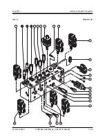
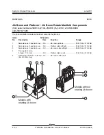
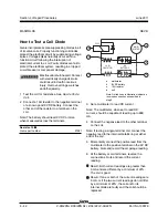
Jib Boom and Platform / Jib Boom Rotate Manifold Components
(before serial numbers Z30N10-12102, Z30N10 (RJ)-12197, Z34N10-8838
and Z3410-7720)
The jib boom/platform rotate manifold is mounted to the jib boom.
Index
Schematic
No.
Description
Item
Function
Torque
1
Solenoid valve, 3 position 4 way .... AA .......... Jib boom up/down ............................ 20-25 ft-lbs / 27-34 Nm
2
Solenoid valve, 3 position 4 way .... AB .......... Platform rotate left/right ..................... 20-25 ft-lbs / 27-34 Nm
3
Solenoid valve, 3 position 4 way .... AC .......... Jib boom rotate left/right ................... 20-25 ft-lbs / 27-34 Nm
4
Flow regulator valve,
0.3 gpm / 1.14 L/min ........................ AD .......... Platform rotate circuit ........................ 20-25 ft-lbs / 27-34 Nm
5
Orifice plug, 0.025 inch / 0.64 mm .. AE .......... Jib boom rotate circuit
(located under plug)
4
5
1
2
3
1
2
4
Models without
rotating jib boom
Models with
rotating jib boom
AA
AB
AC
AD
AA
AB
AE
AD
Summary of Contents for Z-30/20N
Page 1: ......
Page 148: ...6 46 June2011 Section 6 Schematics 6 45 Power Cable Wiring Diagram...
Page 149: ...6 47 Section 6 Schematics June2011 6 48 Drive Contactor Panel Wiring Diagram...
Page 152: ...6 50 June2011 Section 6 Schematics Manifold and Limit Switch Wiring Diagram 6 49...
Page 153: ...6 51 Section 6 Schematics June2011 6 52 LVI BCI Option Wiring Diagram...
Page 156: ...6 54 June2011 Section 6 Schematics 6 53 Charger Interlock Option...
Page 157: ...6 55 Section 6 Schematics June2011 6 56 CTE Option CE Models...
Page 160: ...6 58 June2011 Section 6 Schematics Hydraulic Schematic 6 57...


