Part No. 139378
Z-30/20N • Z-30/20N RJ • Z-34/22 • Z-34/22N
4 - 19
June 2011
Section 4 • Repair Procedures
REV A
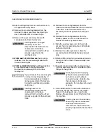
11 Swing the leveling link up out of the way and
secure it from moving.
12 Tag, disconnect and plug the primary boom lift
cylinder hydraulic hoses. Cap the fittings on the
cylinder.
Bodily injury hazard. Spraying
hydraulic oil can penetrate and
burn skin. Loosen hydraulic
connections very slowly to allow
the oil pressure to dissipate
gradually. Do not allow oil to squirt
or spray.
13 Support the barrel end of the primary boom lift
cylinder with straps or ropes to restrict it from
swinging freely.
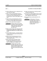
14 Remove the pin retaining fastener from the
primary boom lift cylinder barrel-end pivot pin.
Do not remove the pivot pin.
15 Place a rod through the barrel-end pivot pin and
twist to remove the pin.
Crushing hazard. The primary
boom lift cylinder may fall when
the barrel-end pivot pin is removed
if not properly supported.
16 Attach an overhead crane or similar lifting
device to the lug on the rod-end of the primary
boom lift cylinder. Carefully loosen the straps
and allow the primary boom lift cylinder to
slowly swing down.
17 Carefully remove the cylinder from the machine.
Crushing hazard. The primary
boom lift cylinder will fall if not
properly supported when it is
removed from the machine.
PRIMARY BOOM COMPONENTS
4-4
Extension Cylinder
The extension cylinder extends and retracts the
primary boom extension tube. The extension
cylinder is equipped with counterbalance valves to
prevent movement in the event of a hydraulic line
failure.
How to Remove the
Extension Cylinder
Bodily injury hazard. This
procedure requires specific repair
skills, lifting equipment and a
suitable workshop. Attempting this
procedure without these skills and
tools could result in death or
serious injury and significant
component damage. Dealer
service is strongly recommended.
Note: When removing a hose assembly or fitting,
the O-ring on the fitting and/or hose end must be
replaced and then torqued to specification during
installation. Refer to Section 2,
Hydraulic Hose and
Fitting Torque Specifications.
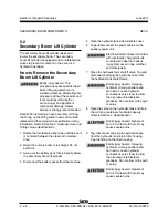
1 Raise the primary boom to the horizontal
position. Extend the boom 3 to 4 feet / 1 m until
the extension cylinder rod-end pivot pins are
accessible.
2 Remove the external snap rings from the
extension cylinder rod-end pivot pins. Use a
soft metal drift to remove the pins.
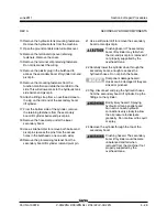
3 Remove the counterweight cover fasteners.
Remove the counterweight cover from the
machine.
4 Raise the secondary boom until the master
cylinder rod-end pivot pin is accessible.
Summary of Contents for Z-30/20N
Page 1: ......
Page 148: ...6 46 June2011 Section 6 Schematics 6 45 Power Cable Wiring Diagram...
Page 149: ...6 47 Section 6 Schematics June2011 6 48 Drive Contactor Panel Wiring Diagram...
Page 152: ...6 50 June2011 Section 6 Schematics Manifold and Limit Switch Wiring Diagram 6 49...
Page 153: ...6 51 Section 6 Schematics June2011 6 52 LVI BCI Option Wiring Diagram...
Page 156: ...6 54 June2011 Section 6 Schematics 6 53 Charger Interlock Option...
Page 157: ...6 55 Section 6 Schematics June2011 6 56 CTE Option CE Models...
Page 160: ...6 58 June2011 Section 6 Schematics Hydraulic Schematic 6 57...

