Part No. 139378
Z-30/20N • Z-30/20N RJ • Z-34/22 • Z-34/22N
2 - 5
Section 2 • Specifications
June 2011
REV C
SPECIFICATIONS
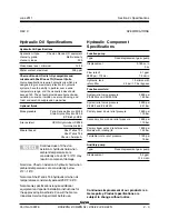
Hydraulic Hose and Fitting
Torque Specifications
Your machine is equipped with Parker Seal-Lok
®
fittings and hose ends. Genie specifications require
that fittings and hose ends be torqued to
specification when they are removed and installed
or when new hoses or fittings are installed.
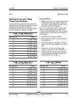
Seal-Lok® fittings
1 Replace the O-ring. The O-ring must be replaced
anytime the seal has been broken. The O-ring
cannot be re-used if the fitting or hose end has
been tightened beyond finger tight.
Note: The O-rings used in the Parker Seal Lok®
fittings and hose ends are custom-size O-rings.
They are not standard SAE size O-rings. They are
available in the O-ring field service kit (Genie part
number 49612).
2 Lubricate the O-ring before installation.
3 Be sure that the face seal O-ring is seated and
retained properly.
4 Position the tube and nut squarely on the face
seal end of the fitting and tighten the nut finger
tight.
5 Tighten the nut or fitting to the appropriate
torque per given size as shown in the table.
6 Operate all machine functions and inspect the
hoses and fittings and related components to
confirm that there are no leaks.
SAE O-ring Boss Port
(tube fitting - installed into Aluminum)
SAE Dash size
Torque
-4
11 ft-lbs / 14.9 Nm
-6
23 ft-lbs / 31.2 Nm
-8
40 ft-lbs / 54.2 Nm
-10
69 ft-lbs / 93.6 Nm
-12
93 ft-lbs / 126.1 Nm
-16
139 ft-lbs / 188.5 Nm
-20
172 ft-lbs / 233.2 Nm
-24
208 ft-lbs / 282 Nm
SAE O-ring Boss Port
(tube fitting - installed into Steel)
SAE Dash size
Torque
-4
16 ft-lbs / 21.7 Nm
-6
35 ft-lbs / 47.5 Nm
-8
60 ft-lbs / 81.3 Nm
-10
105 ft-lbs / 142.4 Nm
-12
140 ft-lbs / 190 Nm
-16
210 ft-lbs / 284.7 Nm
-20
260 ft-lbs / 352.5 Nm
-24
315 ft-lbs / 427.1 Nm
Seal-Lok
®
Fittings
(hose end)
SAE Dash size
Torque
-4
18 ft-lbs / 24.4 Nm
-6
27 ft-lbs / 36.6 Nm
-8
40 ft-lbs / 54.2 Nm
-10
63 ft-lbs / 85.4 Nm
-12
90 ft-lbs / 122 Nm
-16
120 ft-lbs / 162.7 Nm
-20
140 ft-lbs / 190 Nm
-24
165 ft-lbs / 223.7 Nm
Summary of Contents for Z-30/20N
Page 1: ......
Page 148: ...6 46 June2011 Section 6 Schematics 6 45 Power Cable Wiring Diagram...
Page 149: ...6 47 Section 6 Schematics June2011 6 48 Drive Contactor Panel Wiring Diagram...
Page 152: ...6 50 June2011 Section 6 Schematics Manifold and Limit Switch Wiring Diagram 6 49...
Page 153: ...6 51 Section 6 Schematics June2011 6 52 LVI BCI Option Wiring Diagram...
Page 156: ...6 54 June2011 Section 6 Schematics 6 53 Charger Interlock Option...
Page 157: ...6 55 Section 6 Schematics June2011 6 56 CTE Option CE Models...
Page 160: ...6 58 June2011 Section 6 Schematics Hydraulic Schematic 6 57...


