4 - 20
Z-30/20N • Z-30/20N RJ • Z-34/22 • Z-34/22N
Part No. 139378
June 2011
Section 4 • Repair Procedures
REV A
PRIMARY BOOM COMPONENTS
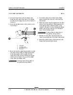
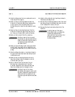
5 Remove the primary boom extend drive limit
switch from the pivot end of the primary boom.
Do not disconnect the wiring.
6 Remove the retaining fastener from the master
cylinder rod-end pivot pin. Use a soft metal drift
to remove the pin.
7 Manually retract the master cylinder and push it
toward the platform end of the boom to obtain
enough clearance for extension cylinder
removal.
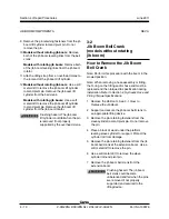
8 Tag, disconnect and plug the extension cylinder
hydraulic hoses. Cap the fittings on the
cylinder.
Bodily injury hazard. Spraying
hydraulic oil can penetrate and
burn skin. Loosen hydraulic
connections very slowly to allow
the oil pressure to dissipate
gradually. Do not allow oil to squirt
or spray.
9 Remove the retaining fastener from the
extension cylinder barrel-end pivot pin. Use a
soft metal drift to remove the pin.
10 Carefully pull out and properly support the
extension cylinder from the primary boom with
a lifting strap from an overhead crane.
Crushing hazard. The cylinder
could fall if not properly supported
when it is pulled out of the
extension tube.
Note: To make installation of the extension cylinder
easier, be sure that the cylinder rod is extended
3 to 4 feet / 1 m.
Note: During removal, the overhead crane strap will
need to be carefully adjusted for proper balancing.
4-5
Platform Leveling Master
Cylinder
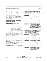
The platform leveling master cylinder acts as a
pump for the slave cylinder. It is part of the closed-
loop hydraulic circuit that keeps the platform level
through the entire range of primary boom motion.
The platform leveling master cylinder is located
inside the upper mid-pivot at the pivot end of the
primary boom.
How to Remove the Platform
Leveling Master Cylinder
Bodily injury hazard. This
procedure requires specific repair
skills, lifting equipment and a
suitable workshop. Attempting this
procedure without these skills and
tools could result in death or
serious injury and significant
component damage. Dealer
service is strongly recommended.
Note: When removing a hose assembly or fitting,
the O-ring on the fitting and/or hose end must be
replaced and then torqued to specification during
installation. Refer to Section 2,
Hydraulic Hose and
Fitting Torque Specifications.
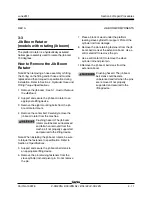
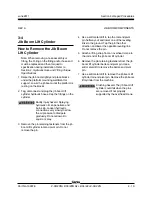
Note: Before cylinder removal is considered, bleed
the cylinder to be sure that there is no air in the
closed loop. See 2-1,
How to Bleed the Slave
Cylinder.
Summary of Contents for Z-30/20N
Page 1: ......
Page 148: ...6 46 June2011 Section 6 Schematics 6 45 Power Cable Wiring Diagram...
Page 149: ...6 47 Section 6 Schematics June2011 6 48 Drive Contactor Panel Wiring Diagram...
Page 152: ...6 50 June2011 Section 6 Schematics Manifold and Limit Switch Wiring Diagram 6 49...
Page 153: ...6 51 Section 6 Schematics June2011 6 52 LVI BCI Option Wiring Diagram...
Page 156: ...6 54 June2011 Section 6 Schematics 6 53 Charger Interlock Option...
Page 157: ...6 55 Section 6 Schematics June2011 6 56 CTE Option CE Models...
Page 160: ...6 58 June2011 Section 6 Schematics Hydraulic Schematic 6 57...

