3 - 26
Z-30/20N • Z-30/20N RJ • Z-34/22 • Z-34/22N
Part No. 139378
Section 3 • Scheduled Maintenance Procedures
June 2011
REV A
D-4
Replace the Drive Hub Oil
Note: Genie specifications require that this
procedure be performed every 1000 hours or
annually, whichever comes first.
Replacing the drive hub oil is essential for good
machine performance and service life. Failure to
replace the drive hub oil at yearly intervals may
cause the machine to perform poorly and
continued use may cause component damage.
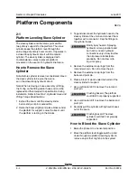
1 Select the drive hub to be serviced. Drive the
machine until one of the two plugs is at the
lowest point.
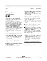
2 Remove both plugs and drain the oil into a
suitable container.
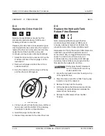
3 Drive the machine until one plug is at the top
and the other is at 90 degrees.
a
drive hub plugs
4 Fill the hub with oil from the top hole until the oil
level is even with the bottom of the side plug
hole. Refer to Section 2,
Specifications.
5 Install the plugs into the drive hub.
6 Repeat this procedure for the other drive hub.
CHECKLIST
D
PROCEDURES
D-5
Replace the Hydraulic Tank
Return Filter Element
Note: Genie specifications require that this
procedure be performed every 1000 hours or
annually, whichever comes first. Perform this
procedure more often if dusty conditions exist.
Replacement of the hydraulic return filter element is
essential for good machine performance and
service life. A dirty or clogged filter element may
cause the machine to perform poorly and
continued use may cause component damage.
Extremely dirty conditions may require that the
filter element be replaced more often.
Bodily injury hazard. Beware of
hot oil. Contact with hot oil may
cause severe burns.
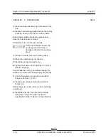
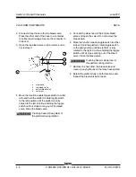
1 Locate the hydraulic return filter housing on top
of the hydraulic tank.
2 Clean the area around the oil filter housing cap
located on top of the reservoir.
3 Remove the cap from the housing.
4 Lift the handle on the filter element and rotate
the element counterclockwise to release the
element from the housing.
5 Remove the filter element from the filter
housing.
a
Summary of Contents for Z-30/20N
Page 1: ......
Page 148: ...6 46 June2011 Section 6 Schematics 6 45 Power Cable Wiring Diagram...
Page 149: ...6 47 Section 6 Schematics June2011 6 48 Drive Contactor Panel Wiring Diagram...
Page 152: ...6 50 June2011 Section 6 Schematics Manifold and Limit Switch Wiring Diagram 6 49...
Page 153: ...6 51 Section 6 Schematics June2011 6 52 LVI BCI Option Wiring Diagram...
Page 156: ...6 54 June2011 Section 6 Schematics 6 53 Charger Interlock Option...
Page 157: ...6 55 Section 6 Schematics June2011 6 56 CTE Option CE Models...
Page 160: ...6 58 June2011 Section 6 Schematics Hydraulic Schematic 6 57...


