Part No. 139378
Z-30/20N • Z-30/20N RJ • Z-34/22 • Z-34/22N
3 - 27
Section 3 • Scheduled Maintenance Procedures
June 2011
REV A
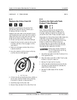
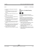
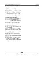
6 Install the new oil filter element into the filter
housing.
7 Push the filter element down to be sure the o-
ring on the element is fully seated into the
housing.
8 Rotate the filter element clockwise to lock it in
place.
9 Install the filter housing cap.
10 Clean up any oil that may have spilled during
the replacement procedure.
11 Use a permanent ink marker to write the date
and number of hours from the hour meter on
the oil filter housing.
12 Turn the key switch to ground controls and pull
out the red Emergency Stop button to the on
position.
13 Move and hold the function enable toggle switch
to either side and move and hold the primary
boom toggle switch in the up direction.
14 Inspect the filter housing and related
components to be sure that there are no leaks.
CHECKLIST
D
PROCEDURES
D-6
Inspect for Turntable Bearing
Wear
Note: Genie requires that this procedure be
performed every 1000 hours or annually, whichever
comes first.
Periodic inspection of turntable bearing wear is
essential to safe machine operation, good machine
performance and service life. Continued use of a
worn turntable bearing could create an unsafe
operating condition, resulting in death or serious
injury and component damage.
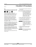
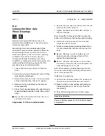
1 Grease the turntable bearing. See A-5,
Grease
the Turntable Bearing and Rotate Gear.
2 Torque the turntable bearing bolts to
specification. See D-3,
Check the Turntable
Rotation Bearing Bolts.
3 Raise the primary and secondary booms to full
height using the ground controls. Do not extend
the primary boom.
Summary of Contents for Z-30/20N
Page 1: ......
Page 148: ...6 46 June2011 Section 6 Schematics 6 45 Power Cable Wiring Diagram...
Page 149: ...6 47 Section 6 Schematics June2011 6 48 Drive Contactor Panel Wiring Diagram...
Page 152: ...6 50 June2011 Section 6 Schematics Manifold and Limit Switch Wiring Diagram 6 49...
Page 153: ...6 51 Section 6 Schematics June2011 6 52 LVI BCI Option Wiring Diagram...
Page 156: ...6 54 June2011 Section 6 Schematics 6 53 Charger Interlock Option...
Page 157: ...6 55 Section 6 Schematics June2011 6 56 CTE Option CE Models...
Page 160: ...6 58 June2011 Section 6 Schematics Hydraulic Schematic 6 57...

