Part No. 139378
Z-30/20N • Z-30/20N RJ • Z-34/22 • Z-34/22N
3 - 15
Section 3 • Scheduled Maintenance Procedures
June 2011
REV B
CHECKLIST
B
PROCEDURES
B-8
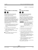
Test the Platform Self-leveling
Note: Genie specifications require that this
procedure be performed every 250 hours or
quarterly, whichever comes first.
Automatic platform self-leveling throughout
the full cycle of boom raising and lowering is
essential for safe machine operation. The
platform is maintained level by the platform leveling
slave cylinder which is controlled by the platform
leveling master cylinder located at the base of the
primary boom. A platform self-leveling failure
creates an unsafe working condition for platform
and ground personnel.
1 Turn the key switch to ground controls and pull
out the red Emergency Stop button to the on
position at both the ground and platform
controls.
2 Lower the boom to the stowed position.
3 Adjust the platform to a level position using the
platform leveling toggle switch.
4 Raise and lower the primary boom through
a full cycle.
Result: The platform should remain level at
all times to within ±5 degrees.
B-9
Test the Drive Brakes
Note: Genie specifications require that this
procedure be performed every 250 hours or
quarterly, whichever comes first.
Proper brake action is essential to safe machine
operation. The drive brake function should operate
smoothly, free of hesitation, jerking and unusual
noise. Hydraulically-released individual wheel
brakes can appear to operate normally when they
are actually not fully operational.
Collision hazard. Be sure that the
machine is not in free-wheel or
partial free-wheel configuration.
Refer to B-5,
Confirm the Proper
Brake Configuration
.
1 Select a test area that is firm, level and free of
obstructions.
2 Mark a test line on the ground for reference.
3 Lower the boom to the stowed position.
4 Turn the key switch to platform controls.
5 Choose a reference point on the machine; i.e.,
contact patch of a tire, as a visual reference for
use when crossing the test line.
6 Bring the machine to top drive speed before
reaching the test line. Release the drive joystick
when your reference point on the machine
crosses the test line.
7 Measure the distance between the test line and
your machine reference point. Refer to
Section 2,
Specifications.
Note: The brakes must be able to hold the machine
on any slope it is able to climb.
Summary of Contents for Z-30/20N
Page 1: ......
Page 148: ...6 46 June2011 Section 6 Schematics 6 45 Power Cable Wiring Diagram...
Page 149: ...6 47 Section 6 Schematics June2011 6 48 Drive Contactor Panel Wiring Diagram...
Page 152: ...6 50 June2011 Section 6 Schematics Manifold and Limit Switch Wiring Diagram 6 49...
Page 153: ...6 51 Section 6 Schematics June2011 6 52 LVI BCI Option Wiring Diagram...
Page 156: ...6 54 June2011 Section 6 Schematics 6 53 Charger Interlock Option...
Page 157: ...6 55 Section 6 Schematics June2011 6 56 CTE Option CE Models...
Page 160: ...6 58 June2011 Section 6 Schematics Hydraulic Schematic 6 57...


