background image

GE H

EALTHCARE


D

IRECTION

 5461425-8EN, R

EVISION

 6

B

RIVO

 XR118 S

ERVICE

 M

ANUAL

Page 272

Chapter 12 - - Set Preferences

4. Upon  releasing  the  associated  detector  successfully,  associated  detector

will be updated as non-associated.

If the detector release failed, the associated detector will not become
non-associated. A popup message will be displayed to indicate user of the
release failure.

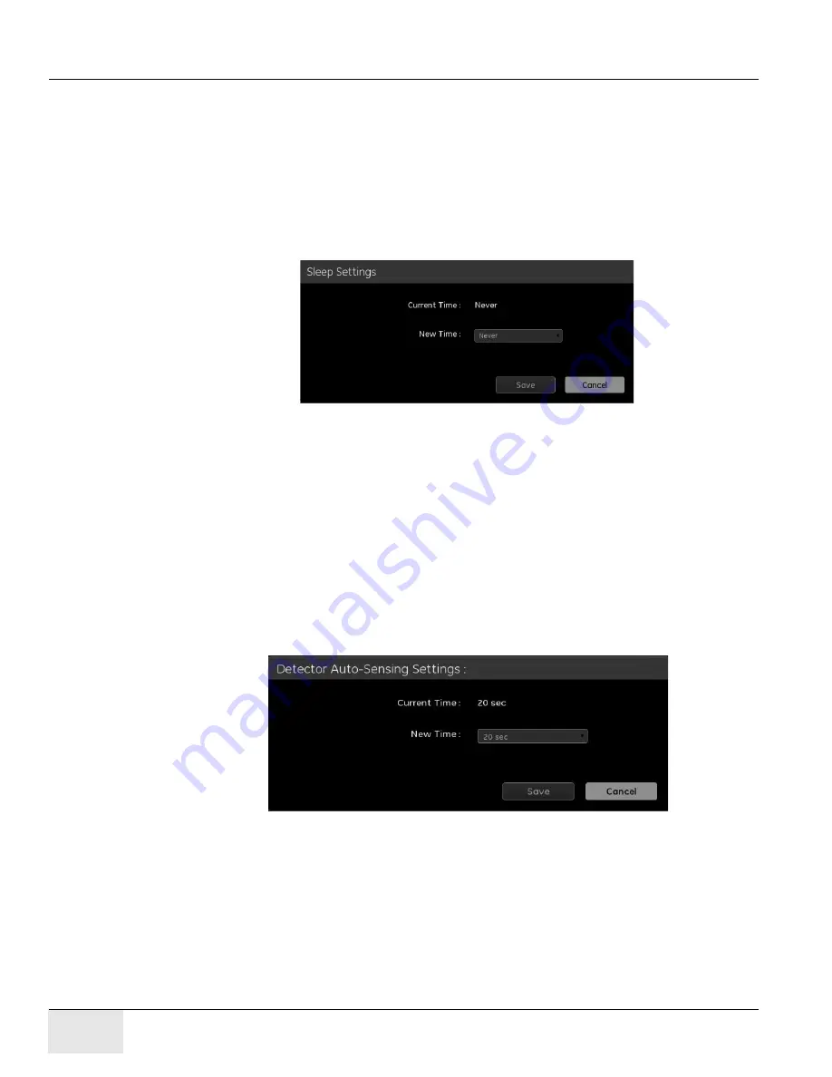
Detector Sleeping Setting

Figure 12-16 

System - Detector Management- Detector Sleep Time

The detector sleep setting window displays the current sleep time of the
associated detector.

Note:

Detector sleep time value means the timeout value from detector’s idle mode to sleep mode. 

If the detector sleeping time is set to 30 minutes, the detector it will
automatically go into the sleeping mode after the system in 30 minutes idle
mode. Once the detector is in sleeping mode you must press the power button on
the detector for one to two seconds to exit the sleep mode. The detector will
wake up and be ready for an exposure in 10 seconds.

Detector Auto-Sensing Setting

Figure 12-17 

System - Detector Management - Detector Auto-sensing Time

The detector autosensing setting window displays the current autosensing time
of the associated detector.

Note:

Detector auto-sensing time means the auto-sensing timeout value from detector entering 
auto-sensing mode.

Summary of Contents for Healthcare Brivo XR118

Page 1: ...Technical Publication GE Healthcare gehealthcare com Direction 5461425 8EN Revision 6 GE Healthcare Brivo XR118 Service Manual Copyright 2015 2019 by General Electric Company Inc ...

Page 2: ...GE HEALTHCARE DIRECTION 5461425 8EN REVISION 6 BRIVO XR118 SERVICE MANUAL Page 2 Published by the GE Company Inc ...

Page 3: ...ipt are trademarks of Adobe Systems Incorporated or its subsidiaries and may be registered in certain jurisdictions Microsoft is a registered trademark and Windows is a trademark of Microsoft Corporation All other products and their name brands are trademarks of their respective holders COPYRIGHTS All Material Copyright 2015 2019 by General Electric Company Inc All rights reserved ...

Page 4: ...GE HEALTHCARE DIRECTION 5461425 8EN REVISION 6 BRIVO XR118 SERVICE MANUAL Page 4 Legal Notes ...

Page 5: ...ž byste si přečetli tento provozní návod a pochopili jeho obsah V případě nedodržování této výstrahy může dojít k poranění pracovníka prodejního servisu obslužného personálu nebo pacientů vlivem elektrického proudu respektive vlivem mechanických či jiných rizik ADVARSEL DA Denne servicemanual findes kun på engelsk Hvis en kundes tekniker har brug for et andet sprog end engelsk er det kundens ansva...

Page 6: ...ninkielistä materiaalia tarvittavan käännöksen hankkiminen on asiakkaan vastuulla Älä yritä korjata laitteistoa ennen kuin olet varmasti lukenut ja ymmärtänyt tämän huolto ohjeen Mikäli tätä varoitusta ei noudateta seurauksena voi olla huoltohenkilöstön laitteiston käyttäjän tai potilaan vahingoittuminen sähköiskun mekaanisen vian tai muun vaaratilanteen vuoksi ATTENTION FR Ce manuel de service n ...

Page 7: ...ikai vagy egyéb veszélyhelyzet miatti sérülését eredményezheti AÐVÖRUN IS Þessi þjónustuhandbók er eingöngu fáanleg á ensku Ef að þjónustuveitandi viðskiptamanns þarfnast annas tungumáls en ensku er það skylda viðskiptamanns að skaffa tungumálaþjónustu Reynið ekki að afgreiða tækið nema að þessi þjónustuhandbók hefur verið skoðuð og skilin Brot á sinna þessari aðvörun getur leitt til meiðsla á þjó...

Page 8: ...nkite atlikti įrangos techninės priežiūros nebent atsižvelgėte į šį eksploatavimo vadovą ir jį supratote Jei neatkreipsite dėmesio į šį perspėjimą galimi sužalojimai dėl elektros šoko mechaninių ar kitų pavojų paslaugų tiekėjui operatoriui ar pacientui ADVARSEL NO Denne servicehåndboken finnes bare på engelsk Hvis kundens serviceleverandør trenger et annet språk er det kundens ansvar å sørge for o...

Page 9: ...лийском языке Если сервисному персоналу клиента необходимо руководство не на английском а на каком то другом языке клиенту следует самостоятельно обеспечить перевод Перед обслуживанием оборудования обязательно обратитесь к данному руководству и поймите изложенные в нем сведения Несоблюдение требований данного предупреждения может привести к тому что специалист по обслуживанию оператор или пациент ...

Page 10: ...är servicehandboken Om du inte tar hänsyn till den här varningen kan det resultera i skador på serviceteknikern operatören eller patienten till följd av elektriska stötar mekaniska faror eller andra faror DIKKAT TR Bu servis kilavuzunun sadece ingilizcesi mevcuttur Eğer müşteri teknisyeni bu kilavuzu ingilizce dişinda bir başka lisandan talep ederse bunu tercüme ettirmek müşteriye düşer Servis kil...

Page 11: ...eld engineers All of GE s electrical work on these products will comply with the requirements of the applicable electrical codes The purchaser of GE equipment shall only utilize qualified personnel i e GE s field engineers personnel of third party service companies with equivalent training or licensed electricians to perform electrical servicing on the equipment IMPORTANT X RAY PROTECTION X ray eq...

Page 12: ...ALTHCARE DIRECTION 5461425 8EN REVISION 6 BRIVO XR118 SERVICE MANUAL Page 12 Important Precautions GE personnel please use the GEHC CQA Process to report all omissions errors and defects in this publication ...

Page 13: ...procedures 3 June 12 2016 Add RIS HIS trouble shooting section 4 Dec 14 2017 Update Detector Calibration Procedure Add 2 Detector Switch Patch Installation Procedure Add several section in Troubleshooting Add 2 FRU 5589170 1 5589170 5 Dec 20 2018 1 Update Chapter 1 to add 4 5 Grounding Resistance Tests 2 Update Chapter 5 to update Leakage Current Test 6 Sep 05 2019 Modify the layout of the yellow ...

Page 14: ...RE DIRECTION 5461425 8EN REVISION 6 BRIVO XR118 SERVICE MANUAL Page 14 List of Effected Pages List of Effected Pages PAGES REVISION PAGES REVISION 1 to 196 1 1 to 196 2 1 to 250 3 1 to 312 4 1 to 318 5 1 to 318 6 ...

Page 15: ...ch specific safety statement 1 1 Hazard Messages Any action that will could or potentially cause personal injury will be preceded by the safety alert symbol and an appropriate signal word The safety alert symbol is the triangle with an exclamation mark within it It s always used next to the signal word to indicate the severity of the hazard Together they are used to indicate a hazard exists Signal...

Page 16: ...d The following Symbols and Pictorials are be used in this publication These graphical icons symbols may be used to make you aware of specific types of hazards that could possibly cause harm Some parts inside are live even after the system is shut down make sure to open the MAINS switch in the power distribution box on the wall and follow LOTO procedure keep_up fragile static_elec keep_dry general...

Page 17: ...rmation possibly stated previously Comment Represents additional information that may or may not be relevant to your situation 2 2 Page Layout Headers and footers in this publication are designed to allow you to quickly identify your location The document part number and revision number appears in every header on every page Odd numbered page footers indicate the current chapter its title and curre...

Page 18: ...t This paragraph s font represents fixed input It s computer input that is typed in via the keyboard Typed input that does not vary from application to application or system to system Fixed text the user is required to supply as input For example cd usr 3p Example Variable Input This paragraph s font represents computer input that can vary from application to application or system to system With v...

Page 19: ...m Power 25 Section 3 0 De Energizing System 26 Section 4 0 Equipment Safety Electrostatic Discharge ESD 27 Chapter 2 Before You Begin 29 Section 1 0 Introduction 29 Section 2 0 Objective and Scope of this Manual 29 Section 3 0 On Site Requirements 31 Section 4 0 Description of System 31 Section 5 0 Installation Process 32 Chapter 3 Installation Guide 33 Section 1 0 Steps for system installation 33...

Page 20: ...on 52 Section 6 0 Detector Installation 54 Section 7 0 System Power Up 57 Section 8 0 Software Installation 58 Section 9 0 System Configuration 69 Section 10 0 Detector Association 112 Section 11 0 AP Assembly Installation 117 Section 12 0 Leakage Current Test 122 Section 13 0 Rating Plates 125 Section 14 0 Installation Checklist 126 Chapter 6 Calibration 129 Section 1 0 Before You Begin 129 Secti...

Page 21: ...ction 9 0 Printer Calibration 141 Section 10 0 PACS Image Display Test Image 141 Chapter 7 Brivo XR118 System Check 155 Section 1 0 Image Quality Test 155 Section 2 0 Image Artifact Check Optional 155 Section 3 0 Uniformity Check 155 Section 4 0 Acquisition Test 156 Section 5 0 Regulatory Test 156 Chapter 8 Troubleshooting 159 Section 1 0 Hardware Failure 159 Section 2 0 Software Issues 172 Sectio...

Page 22: ...n 1 0 General 217 Section 2 0 Preventive Maintenance Action List 218 Section 3 0 Preventive Maintenance 220 Chapter 10 Renewal parts 223 Section 1 0 System Components 223 Section 2 0 Digital Detector 235 Chapter 11 Master Interconnect System Map 239 Section 1 0 Scope 239 Section 2 0 Symbols Conventions 239 Section 3 0 Digital System MIS Map 240 Chapter 12 Set Preferences 241 ...

Page 23: ...rsonnel notified by verbal communication Energy Source Yes No Location of Energy Isolat ing Means Magnitude of Energy Pneumatic Yes System s Cabi net Power Dis connect 100 127vac or 200 240vac Single Phase Hydraulic No Gas Water Steam No Chemical No Mechanical Motion No Gravity No Springs No Thermal No Stored Energy No Air Under Pressure No Oil Under Pressure No Water Under Pressure No Gas Under P...

Page 24: ...voltmeter measure the incoming power connection to the system cabinet at the circuit breaker 6 If no voltage is present at the system cabinet s circuit breaker place the power switch on the Cabinet to the OFF position and service equipment as required 7 After service has been performed notify affected personnel that equipment will be re energized and LOTO devices are being removed 8 Assure the saf...

Page 25: ...ers up safely properly and reliably Potential for Equipment Damage Cabinet settings must match input voltage else there is potential for equipment damage The power cord plug complies with the local national standard 2 2 Energizing System The Brivo XR118 system is designed to function totally independent of the X ray RAD target system without any hardware connection So its power up is controlled by...

Page 26: ...ERVICE MANUAL Page 26 Section 3 0 De Energizing System Section 3 0 De Energizing System Shut down is controlled by its own power socket There is no recommended shutdown sequence for XR118 system and target system Complete shutdown takes approximately 80 Seconds ...

Page 27: ...ry to prevent damage to electric components and accessories Transport products in static safe containers such as tubes bags or boxes to avoid hand contact Protect all electrostatic parts and assemblies with conductive or approved containers or packaging Keep electrostatic sensitive parts in their containers until they arrive at static free stations Place items on a grounded surface before removing...

Page 28: ...n fixtures must directly contact dissipative surfaces Keep work area free of non conductive materials such as ordinary plastic assembly aids and Styrofoam 4 4 Recommended Materials and Equipment Materials and equipment that are recommended for use in preventing static electricity include One set of monitor with keyboard mouse Only required by Mobile mode Antistatic tape smocks aprons or sleeve pro...

Page 29: ...ISK OF ELECTRIC SHOCK VOLTAGE PRESENT THE SYSTEM MUST BE DISCONNECTED FROM THE FACILITY MAINS INCLUDING THE A1 PANEL GROUND WIRE 4 5 4 Required Conditions 4 5 5 Set up tools How to connect the Tool 1 Connect power cord 2 Connect red test lead to red input jack V Ω A 3 Connect black test lead to black input jack Personnel Requirements Preliminary Reqs Procedure Finalization 1 Not Applicable 30min 1...

Page 30: ...itional menu selections 3 Press F2 button under the softkey labeled Instrument to reveal the instrument setup selections 4 Press F1 button under the softkey labeled Standard to open the scroll box above the softkey label 5 Press button of UP or Down to scroll through the standard selections 6 When the desired standard is displayed press F1 button under the softkey labeled Standard to confirm the s...

Page 31: ...ad to power cord PE pin Connected the alligator clip of the red test lead to test point 4 Record the protective earth resistance value The protective earth resistance value should not be greater than 0 3 Ω 300 mΩ 4 5 7 Protective Earth Resistance Test Procedure 1 The PC adapter output shielding 2 After protective earth resistance test reconnect the PC adapter output to PC terminal No TEST POINT Ex...

Page 32: ...GE HEALTHCARE DIRECTION 5461425 8EN REVISION 6 BRIVO XR118 SERVICE MANUAL Page 32 Section 4 0 Equipment Safety Electrostatic Discharge ESD ...

Page 33: ...to install the system identify all the cables and check their length to verify that they are long enough If you find a short cable contact us immediately so we can send the required length cable to you and thereby not delay the installation 2 1 Pre Installation Check Pre installation planning should be complete Inspect the pre installation checklist found in GEHC document 5461785 8EN Brivo XR118 S...

Page 34: ...hed cables or contractor supplied wiring is indicated by numbered MIS runs in the installation sections Run interconnect charts are available which describe the connection and function of each wire For Brivo XR118 System refer to the following Brivo XR118 System MIS Map Brivo XR118 System MIS Chart 2 4 Presentation The procedures in this steering manual are presented in job card forms ...

Page 35: ...re installing the Brivo XR118 System as below Common service tools Screwdriver T10 3 2 Documentation Directions are necessary for correct installation of the Brivo XR118 System Procedures from each document will be used and reflect the latest information available at this time Not all procedures in this manual apply to all sites Before you begin installation cross out the procedures that do not ap...

Page 36: ...tion Process The Brivo XR118 System for fixed RAD is divided in to basic components Section 5 0 Installation Process See System Installation Road map Applied Time Standards on the next page 1 Digital Detector 2 Workstation 3 Dock 4 19 LCD Monitor 5 Access Point 6 Power Input Standard Adapter 7 Bar Coder ...

Page 37: ...d transport equipment to room 4 Control Room People Required 1 Minutes to Complete 5 Control Room Placement 5 MIS Cable Connections People Required 1 Minutes to Complete 5 Connect MIS Cable 6 AP Assembly Preparation Fixed RAD system only People Required 1 Minutes to Complete 5 AP Connection and Placement 7 Detector Installation People Required 1 Minutes to Complete 5 Table Upgrade Wallstand Upgrad...

Page 38: ...EC Optional 15 Leakage Tests People Required 1 Minutes to Complete 15 Leakage Tests 16 Labels and Rating Plates People Required 1 Minutes to Complete 5 Attach labels and rating plates 17 Installation Check List People Required 1 Minutes to Complete 10 Complete Installation Check List ...

Page 39: ...als been provided 8 Support structures installed for floor and wall mounted equipment 9 Has floor been modified for cable ducts 10 Electrical service in place at the ratings specified in pre installation documentation 11 Power available to operate power tools 12 All non electrical lines air water oxygen vacuum installed Interconnections Completed 1 Signal cable power and grounding plans produced 2...

Page 40: ...completed 6 Old equipment within room removed 7 Component positions clearly marked on floor 8 Space available to store equipment 9 Lock on door or locked room available 10 Room IP Addresses for DICOM and Broadband identified 11 Broadband connection provided for InSite connection 12 Have all fire safety inspections for occupancy been completed 13 Send completed checklist to the GE Healthcare instal...

Page 41: ...er and reviewed by the installation specialist 12 Packing materials disposed of 13 Have all calibrations been completed 14 Have purchased options been installed enabled configured 15 All appropriate regulatory labels installed Warning labels Rating plates 16 InSite checkout completed 17 Have functional checks been completed 18 Have all protective tape coverings been removed 19 Are there any appear...

Page 42: ...tallation Handoff Checklist ___________________________________ Field Engineer Signature 27 Has backup of original system been performed Patient Data Base as well as total system backup 28 Has Application Specialist received all checklists Pre Installation Installation checklist Item Item Sign Off ...

Page 43: ...igher than 400Hz e Suggest the hospital to ask RIS engineer also to be on site for DICOM connectivity in case RIS query issue occurs it often needs RIS side s update to meet DICOM3 0 2 Make sure the target system meets all the requirements below For more information please contact your sales representative Table 4 1 Target System Requirements No Categor y Item Preferred Capability Target System Cl...

Page 44: ... obvious or the image is distorted after the image reprocessed using the configuration shown as below then it s recommended to change the grid Note For following scenario please turn off the GLR algorithm in Utility Image Processing Grid Line Reduction Single Energy Bucky vibration grid No grid The recommended grid type is 70LP CM 10 System Regulatory Shall comply with local medical equipment regu...

Page 45: ... System Check Page 45 60 LP CM 60LP CM 62 LP CM 36LP CM 60LP CM 64 LP CM 36LP CM 66 LP CM 36LP CM 68 LP CM 70LP CM 70 LP CM 70LP CM 72 LP CM 70LP CM 78LP CM 74 LP CM 70LP CM 78LP CM 76 LP CM 78LP CM 78 LP CM 78LP CM 80 LP CM 70LP CM 78LP CM Target System Grid Type Recommend Grid Type for GLR ...

Page 46: ...GE HEALTHCARE DIRECTION 5461425 8EN REVISION 6 BRIVO XR118 SERVICE MANUAL Page 46 ...

Page 47: ...he number and sizes of interconnecting wiring and proper power availability in the room Do not discard any packing materials such as envelopes boxes bags until all parts are accounted for against the packing list The distribution center or factory must be notified immediately of any damage or shortage of parts Three standard boxes will be delivered Main box monitor and detector box If optional par...

Page 48: ...should not be disconnected in order to pull the cable s through the conduits or wall ducts Power cables must be kept separate from signal cables as much as possible In wall ducts or raceway power cables should be routed in a separate channel from signal cables Power cables should not be bundled together with signal cables All MIS cables should be routed through the conduits or wall ducts as rat pr...

Page 49: ...tem package or components two man lift is required Be careful not exposure to the sharp edge of broken components Figure 5 3 Components for Fixed RAD system Components list for Fixed RAD system 1 Image Workstation 2 Keyboard 3 DVD drive 4 PoE cable 5 Dock 6 Access Point 7 Bar Coder Optional 8 Open Me First Box 9 Power cable Optional 10 Power Adapter 11 Detector Battery ...

Page 50: ...EN REVISION 6 BRIVO XR118 SERVICE MANUAL Page 50 Section 3 0 Unpacking Main Box Open pink box OPEN ME FIRST box at first Take out the Manual CD Read Manuals carefully before system installation and calibration Figure 5 4 Open Me First ...

Page 51: ...e 51 3 1 Recommended Control Room Placement Position the components according to the site plan 3 1 1 Unpacking Components Boxes Figure 5 5 Unpacking Components Boxes 3 1 2 Room Layout It s recommended to place the XR118 system near to the target system console Figure 5 6 Recommended Placement Dock Image Workstation ...

Page 52: ...ADE BY DATE ECR NO DESCRIPTION MADE OTHER APPROVALS YY MM DD CHECK APPR 2 Initial relase Detector 5501661 Dock 5505863 iServer 5500786 Monitor 5498484 Wireless AP 5501606 80pin Connector Ethernet Barcoder B1100LJ Mouse 5537182 Keyboard 5505449 DVD Driver 5539067 USB USB DVI D Detector Battery Charging Slot x2 Power Adaptor USB 100 240VAC 5501567 DC Power 100 240VAC 5501567 Hospital Main Power Wi F...

Page 53: ...UAL Chapter 5 Installation Configuration Page 53 1 Connect image workstation embedded battery 2 Connect switching power supply with power plug Demount the battery cover Remove the cover Battery connector Connect the battery connector and Remount the cover Screwdriver T10 ...

Page 54: ...EVISION 6 BRIVO XR118 SERVICE MANUAL Page 54 Section 4 0 MIS Cable Connections 3 Connect switching power supply to Dock s DC power port 4 Connect Bar coder USB DVD driver to Dock s USB ports 5 Connect the Keyboard Mouse to Dock s USB port ...

Page 55: ...ble from Dock s ethernet port to Hospital s network If required Note Ethernet PoE port shall be only used to connect wireless AP 8 Insert the image workstation into dock s charging slot Note Insert the workstation with the GE side facing the front side of dock to ensure proper orientation 9 Connect monitor s power cable to Hospital main power 10 Connect power plug to Hospital main power Hospital N...

Page 56: ...lace it at Default location or Adjusting range according to room layout 5 1 AP assembly connection 5 1 1 Unpacking Figure 5 8 Unpack AP assembly PoE ethernet cable 5 1 2 Connection 1 Take out wireless AP and PoE Ethernet Cable 2 Connect the PoE ethernet cable from Dock s ethernet PoE port to AP which will be located in the exam room Note The end which has USB connector should be used to connect AP...

Page 57: ...3 then Default Location 2 Note For all locations the distance between AP and detector should be less than 4 meters 4 If all three recommended installation points are all not available follow the instructions in AP Assembly Installation on page 122 to test the wireless signal quality in the adjusting range to find a proper location to place the AP Table WS Default Location Adjusting Range Detector ...

Page 58: ...Detector Installation Section 6 0 Detector Installation 6 1 Unpacking There are two locks on each side of detector package Figure 5 10 Detector Package Figure 5 11 Remove the locks Pull out the knob Rotate the knob to align with notches of the shell Knob Shell Notch Alignment Take out the shell ...

Page 59: ...charged battery in the battery footprint in the detector so that the contacts on the back edge of the battery are inserted first 6 3 Detector Battery Charging Batteries are shipped at 30 to 50 state of charge It s recommended to charge the battery before the first usage If the battery capacity is low see the detector LED color definition in Operating Manual please use the charging slots on system ...

Page 60: ... Wall stand upgrade 1 Remove the film cassette from the wallstand housing if any 2 Insert the image detector into the wallstand housing Brivo XR118 detector is about 3 5kg which is heavier than casette used in analog system After the upgrade balance weight for wallstand cassette housing is required 6 4 3 Detector Operation Wake up Press and hold the power button for more than 2 seconds to wake up ...

Page 61: ...r Supply and monitor power cable into hospital main power If required 2 The dock and AP automatically boot up 3 Press the power button of the monitor 4 Press the power button on the image workstation 2 seconds to power up the workstation 5 Press the power button on the image detector 2 seconds to power up the detector Note Do Not unplug the image workstation from the dock ...

Page 62: ...d backup to restore Note Configure the Time Zone after software re installation or upgrade Note The system is delivered with software installed Only software configuration is required for the new site installation 8 2 System Data Backup Files within the workstation need to be saved if system software is reload upgraded or becomes corrupted After system installation saved files can be restored in t...

Page 63: ... the operators manual for procedures 8 2 2 Backup System Files 1 From the application desktop click on the Utilities icon 2 Click on Launch button 3 Select the Utilities Tab 4 Click on the plus sign preceding the System folder ICON in the navigation frame 5 Click on Backup link 6 Media Selection CD DVD media and USB flash drives are now supported USB flash drives must not contain any volume labels...

Page 64: ...e environment 1 From the Worklist screen click Utilities icon The Service Tools screen appears 2 Select Preferences first and then Protocols from the menu 3 Insert a blank CD DVD into the CD tray and close 4 Click Back up 5 A message will appear Press OK to continue with Protocol Database back up 6 Press OK after you see the message The protocol database is saved to the CD DVD 7 Remove the CD DVD ...

Page 65: ...t Store Optimally Automatically checks if the selected images will fit on the CD It will automatically deselect any items that cannot fit onto the CD Write Begins the copy process Cancel Closes the screen and returns you to the Image Management screen 5 Confirm that the exams to be copied are the ones you have chosen Deselect any exams you do not want saved to the CD DVD 6 Click on Write a The CD ...

Page 66: ...ur system software completely The following procedure installs both the operating system and application software Pay particular attention if instructed to system resets It s important that power be cycled according to a specified procedure Cycling power at the wrong time or by the wrong method can result in a PC s operating file system Linux becoming corrupted If the OS on the PC gets corrupted y...

Page 67: ... No continue on to the next step Backup System Files 3 Backup System Files Please refer to Backup System Files on page 63 4 Backup Protocol Data Base and System Images Please refer to Backup Protocol Data Base on page 64 and Backup Images on page 65 5 Load the system software i Press and hold the Power button of workstation for about 3 seconds ii Place the XR118 software DVD into the USB DVD drive...

Page 68: ...lation starts Figure 5 13 System Installation Step 1 iv Be patient it takes approximately 15 minutes for the system software to load v After the system software installed successful the workstation reboots automatically vi When the boot Menu is displayed again select Boot from first hard disk and press the Enter key Figure 5 14 System Installation Step 2 ...

Page 69: ...tector then perform configuration and calibration tasks If the new system is configured with more than one detector then run Section 8 3 5 Detectors Switch Software Patch Installation Procedure then perform configuration and calibration tasks 8 3 5 Detectors Switch Software Patch Installation Procedure In order to keep 2 detectors switch time shorter than 30s need to run below procedure after Sect...

Page 70: ...on sudo su mount o loop dev sr0 mnt cdrom cd mnt cdrom InstallPatch sh 4 Wait for message Note atlasidc_step9_patch_release 2017_FW36 5 RC1 1 x86_64 rpm patch installation completed Please restart system 5 Then perform below command cd umount mnt cdrom 6 Restart system via iServer power button 7 Eject CD 5589170 1 ...

Page 71: ...because of the files that have been changed A system Reset must be performed after restoring the OS Configuration files to continue using the SUIF You must have a good backup of the files you wish to restore from CD DVD The Backup media can only be inserted after the restore utility screen is displayed 8 4 2 Restore System Files 1 From the application desktop click on the Utilities icon 2 Click on...

Page 72: ...n arrow in the drop down box to display a drop down list of items 8 Click on the item you wish to restore 9 Click on Continue 10 When restore is complete you will see Restore success in the status bar 11 Restore other items with the same procedures 12 Remove Cal Config Backup CD DVD 13 Exit SUIF 14 Shutdown and restart the workstation ...

Page 73: ...store it in a safe place 8 4 4 Restore System Images 1 Use the Eject option in Image Tools button to open the CD tray on the PC 2 Select Eject CD from the drop down list The DVD drive tray will open 3 Place the CD DVD with the images onto the tray and close 4 Click the Media button The exam list updates to now show you the images stored on the CD DVD 5 Select the exams you wish to retrieve using t...

Page 74: ...Parameters 9 1 2 Missing or Lost System Backups If you perform a software install and do not restore configuration files you must re perform all of configurations listed in after it s complete A software install resets all configuration data If you performed a backup before you began the software install you are not required to perform the configuration and calibrations Simply restore the data sav...

Page 75: ...cific location Hospital clinic where system is installed 64 characters maximum Street Address 1 Address of location system is installed 5 lines and 64 characters maximum per line Street Address 2 Address of location system is installed 5 lines and 64 characters maximum per line City City of location system is installed 5 lines and 64 characters maximum per line State Province State Province of loc...

Page 76: ...hoose the country appropriate for your installation The default value is China Measurement System Used to define English or Metric as the system s measurement system The default value is metric Encoding Three options provided ISO_IR 100 ISO_IR 192 and GB18030 GB18030 is only for chinese ISO_IR 192 is for chinese and russian SO_IR 100 is for other languages If simplified chinese input is required p...

Page 77: ...DHCP server on the hospital network If static IP is assigned by hospital this item should be set as disabled No IP Address Fixed Only 16 characters maximum mandatory for Static IP configuration Subnet Mask Fixed Only 16 characters maximum mandatory for Static IP configuration Default Gateway Fixed Only 16 characters maximum Note If the customer site does not have a default gateway use the default ...

Page 78: ...nd Power Setting After selected and committed the change reset system Parameter Definition Echo to AP About 140 seconds after hard AP is powered on system boots up confirm both 5GHz and 2 4GHz LEDs are solid ON then click this button to test the connection between workstation and AP Parameter Definition Working Channel Select The working channel shall follow the latest wireless regulatory or sugge...

Page 79: ...ptions PNF is configured using the SUIF Service User Interface 9 6 2 1 Tabs 1 Named Services Turn on common network services by name i e telnet ftp instead of by port number Can allow communication from a specific IP address a range of IP addresses or a masked subnet Possible to add multiple IP rules for a single service 2 Allowed Nodes Allows all communication over any port from a specified IP Ca...

Page 80: ...rvice office as Standard 150 2 0 0 16 and Access Level as Pre defined setting for encrypted access 9 6 2 2 Buttons 1 Firewall Top Box Turns firewall on and off When the firewall is off all network traffic in both directions are allowed 9 6 3 Configuration Note You should always perform a system reset after modifying any of the PNF options 9 6 3 1 TVA RCOC Open the Service User Interface ...

Page 81: ...cp from the Protocol drop down list III Enter 150 2 0 0 255 255 0 0 as the Allowed IP s IV Click on Add b Port 5900 I Enter the Port number 5900 II Choose tcp from the Protocol drop down list III Enter 150 2 0 0 255 255 0 0 as the Allowed IP s IV Click on Add 4 Click on Apply 9 6 3 2 System Installation 1 The Default configuration for the firewall should be On If Off is selected set it to On and A...

Page 82: ...ith these privileges are allowed access to all system features and operation Admin Service Gives complete control over protocols and user accounts The Admin Service account includes all of the privileges defined for a typical Radiologist account The difference is that the Admin Service account can also create and maintain user accounts root Can only create user accounts User accounts must be creat...

Page 83: ...n a command window 4 At the login prompt type xruser 5 Enter the password 4 xray 6 Insert Operators manual CD into the tray of DVD drive PC 7 To run the inter active script at prompt type the following xrdinstall om click ENTER key 8 A message is displayed Do you want to proceed Enter y click ENTER key 9 Below message is displayed Select the language to install 1 for English 2 for French 3 for Spa...

Page 84: ...9 1 1 Host Tab Table 12 7 Host Tab 9 9 1 2 Preference Tab Values for each network node are configured using the Workstation PC Generally options 1 2 and 3 are enabled checked for remote viewing stations PACS etc Option 1 Check this option if the remote host being configured should be able to Query and get a response of a list of images on the workstation PC Option 2 Check this option if the remote...

Page 85: ...to accept MPPS messages from the magic Options 8 Should be selected if the network host is HIS RIS system Options 9 If selected Image will be sent to this network node as CR format Table 12 8 Preference Tab Option Attribute Value 1 Allow this host to query the system name 2 Allow this host to retrieve from the system name 3 Allow this host to send images to the system name 4 This network host acce...

Page 86: ...inter connectivity Table 12 9 Printer Tab Table 12 10 Layout Tab Table 12 11 Film Size Tab Table 12 12 Printer Settings Tab Attribute Host Device 1 Host Device 2 Host Device 3 DICOM Printer Label Application Entry Title Network Address Port Number Pixel Depth Printer Pixel Size micron Configuration Information Density Magnification Type Smooth Factor Trim Polarity Border Density Empty Image Densit...

Page 87: ...5461425 8EN REVISION 6 BRIVO XR118 SERVICE MANUAL Chapter 5 Installation Configuration Page 87 Magnification Alternative Print Mode Alternative Magnification Orientation Media Type Destination Media Size Format Attribute Value ...

Page 88: ...plication Entry Title Enter value given by Site Network Administrator AE Titles may be site specific be sure to check on site IPNetwork Address Enter value given by Site Network Administrator Port Number 104 Port number may be site specific be sure to check on site Pixel Depth 12 Printer Pixel Size micron 79 4 Configuration Information PERCEPTION_LUT LINEAR no spaces Density Min 20 Max 300 Magnifi...

Page 89: ... 24 x 24cm Pixel Width Pixel Height 24 x 30cm Pixel Width Pixel Height General Comments Supports Clear and Blue Film If medium selected Clear Paper does not match the printer the job will be queued until the correct film is loaded AGFA layouts are specific to maximum printable area layouts Please consult the AGFA technical representative to install custom layouts Only 14x17 film was tested with th...

Page 90: ...4 1 1 P 9014 11 x 14 1 2 P 9102 11 x 14 2 1 P 9103 11 x 14 2 2 P 9104 11 x 14 1 1 L 9018 11 x 14 1 2 L 9202 11 x 14 2 1 L 9203 11 x 14 2 2 L 9204 8 x 10 1 1 P 9006 8 x 10 1 2 P 9009 8 x 10 2 1 P 9008 8 x 10 2 2 P 9010 8 x 10 1 1 L 9007 8 x 10 1 2 L 9012 8 x 10 2 1 L 9011 8 x 10 2 2 L 9013 FILM SIZE FORMAT P L AGFA LAYOUT ...

Page 91: ... value given by Site Network Administrator AE Titles may be site specific be sure to check on site IP Address Enter value given by Site Network Administrator Port Number 104 Pixel Depth 12 Printer Pixel Size micron 55 Configuration Information LUT 0 0 Density Min 20 Max 300 Magnification Type CUBIC Smooth Factor 140 Trim NO Not Supported Polarity NORMAL Border Density BLACK Empty Image Density BLA...

Page 92: ...Width 4880 Pixel Height 5280 10 x 14in Pixel Width Pixel Height 11 x 14in Pixel Width Pixel Height AGFA Layout Portrait 9014 14 x 14in Pixel Width Pixel Height 14 x 17in Pixel Width 6922 Pixel Height 7788 AGFA Layout Portrait 2411 24 x 24cm Pixel Width Pixel Height 24 x 30cm Pixel Width Pixel Height TAB Attribute Value Comments FILM SIZE FORMAT P L AGFA LAYOUT 14 x 17 1 1 P 2411 14 x 17 1 2 P 9001...

Page 93: ...18 SERVICE MANUAL Chapter 5 Installation Configuration Page 93 11 x 14 2 2 L 9204 8 x 10 1 1 P 9006 8 x 10 1 2 P 9009 8 x 10 2 1 P 9008 8 x 10 2 2 P 9010 8 x 10 1 1 L 9007 8 x 10 1 2 L 9012 8 x 10 2 1 L 9011 8 x 10 2 2 L 9013 FILM SIZE FORMAT P L AGFA LAYOUT ...

Page 94: ...04 Pixel Depth 12 Printer Pixel Size micron 100 Configuration Information CS000 Density Min 20 Max 300 Magnification Type CUBIC Smooth Factor SHARP Trim NO Not Supported Polarity NORMAL Border Density BLACK Empty Image Density BLACK Printer Memory Size 40Mbytes Layout Select the desired layouts allowed for this printer 1 1 1 2 2 1 2 2 Slide formats Not Applicable Film Size 8 x 10in Pixel Width 199...

Page 95: ... The following configurations must be configured by the Fuji printer representative to print correctly sized images LUT1 as SAR17 for calling AE_TITLE Trim width at 1 pixel for calling AE_TITLE Globally configure a margin between image for 0 pixels Globally configure Image layout for spread TAB Attribute Value Comments ...

Page 96: ...ntry Title Enter value given by Site Network Administrator AE Titles may be site specific be sure to check on site IP Address Enter value given by Site Network Administrator Port Number 104 Port numbers may be site specific be sure to check on site Pixel Depth 12 Printer Pixel Size micron 84 67 Configuration Information CS000 Density Min 20 Max 300 Magnification Type CUBIC Smooth Factor SHARP Trim...

Page 97: ... Pixel Height 4096 14 x 14in Pixel Width Pixel Height 14 x 17in Pixel Width Pixel Height 24 x 24cm Pixel Width Pixel Height 24 x 30cm Pixel Width Pixel Height The following configurations must be configured by the Fuji printer representative to print correctly sized images LUT1 as SAR17 for calling AE_TITLE Trim width at 1 pixel for calling AE_TITLE Globally configure a margin between image for 0 ...

Page 98: ...trator AE Titles may be site specific be sure to check on site IP Address Enter value given by Site Network Administrator Port Number 104 Port numbers may be site specific be sure to check on site Pixel Depth 12 Printer Pixel Size micron 84 67 Configuration Information CS000 Density Min 20 Max 300 Magnification Type CUBIC Smooth Factor SHARP Trim NO Not Supported Polarity NORMAL Border Density BLA...

Page 99: ...Height 24 x 30cm Pixel Width Pixel Height The following configurations must be configured by the Fuji printer representative to print correctly sized images LUT1 as SAR17 for calling AE_TITLE Trim width at 1 pixel for calling AE_TITLE Globally configure a margin between image for 0 pixels Globally configure Image layout for spread A densitometer filter FUJI part number 605S0003 must be used when p...

Page 100: ...ork Administrator AE Titles may be site specific be sure to check on site IP Address Enter value given by Site Network Administrator Port Number 104 Port numbers may be site specific be sure to check on site Pixel Depth 12 Printer Pixel Size micron 50 Configuration Information CS000 Density Min 20 Max 300 Magnification Type CUBIC Smooth Factor SHARP Trim NO Not Supported Polarity NORMAL Border Den...

Page 101: ...e 8 x 10in Pixel Width 3907 Pixel Height 4819 10 x 12in Pixel Width Pixel Height 10 x 14in Pixel Width 5075 Pixel Height 7043 11 x 14in Pixel Width Pixel Height 14 x 14in Pixel Width Pixel Height 14 x 17in Pixel Width Pixel Height 24 x 24cm Pixel Width Pixel Height 24 x 30cm Pixel Width Pixel Height TAB Attribute Value Comments ...

Page 102: ...ck on site IP Address Enter value given by Site Network Administrator Port Number 1024 Port numbers may be site specific be sure to check on site Pixel Depth 12 Printer Pixel Size micron 78 15 Configuration Information LUT Wkstn2a w87 2 no spaces Density Min 20 Max 300 Magnification Type CUBIC Smooth Factor 15 Trim NO Polarity NORMAL Border Density BLACK Empty Image Density BLACK Printer Memory Si...

Page 103: ...m Size 8 x 10in Pixel Width Pixel Height 10 x 12in Pixel Width Pixel Height 10 x 14in Pixel Width Pixel Height 11 x 14in Pixel Width Pixel Height 14 x 14in Pixel Width Pixel Height 14 x 17in Pixel Width 3388 Pixel Height 4277 24 x 24cm Pixel Width Pixel Height 24 x 30cm Pixel Width Pixel Height TAB Attribute Value Comments ...

Page 104: ...ck on site IP Address Enter value given by Site Network Administrator Port Number 1024 Port numbers may be site specific be sure to check on site Pixel Depth 12 Printer Pixel Size micron 78 15 Configuration Information LUT Wkstn2a w87 2 no spaces Density Min 20 Max 300 Magnification Type CUBIC Smooth Factor 15 Trim NO Polarity NORMAL Border Density BLACK Empty Image Density BLACK Printer Memory Si...

Page 105: ...m Size 8 x 10in Pixel Width Pixel Height 10 x 12in Pixel Width Pixel Height 10 x 14in Pixel Width Pixel Height 11 x 14in Pixel Width Pixel Height 14 x 14in Pixel Width Pixel Height 14 x 17in Pixel Width 4096 Pixel Height 5221 24 x 24cm Pixel Width Pixel Height 24 x 30cm Pixel Width Pixel Height TAB Attribute Value Comments ...

Page 106: ...eck on site IP Address Enter value given by Site Network Administrator Port Number 1024 Port numbers may be site specific be sure to check on site Pixel Depth 12 Printer Pixel Size micron 78 1 Configuration Information LUT Wkstn2a w87 2 no spaces Density Min 20 Max 300 Magnification Type CUBIC Smooth Factor 15 Trim NO Polarity NORMAL Border Density BLACK Empty Image Density BLACK Printer Memory Si...

Page 107: ... Width 4096 Pixel Height 5221 24 x 24cm Pixel Width Pixel Height 24 x 30cm Pixel Width Pixel Height The following configurations must be configured by the Kodak printer representative Calling AE_TITLE must be declared in 9410 host table or print will be rejected Pixel correction turned off TFT emulation enabled Landscape printing will be functional only if a Kodak 8800 is installed Note User will ...

Page 108: ... Titles may be site specific be sure to check on site IP Address Enter value given by Site Network Administrator Port Number 1024 Port numbers may be site specific be sure to check on site Pixel Depth 12 Printer Pixel Size micron 38 Configuration Information LUT Ver693c0 w87 6 Density Min 20 Max 300 Magnification Type CUBIC Smooth Factor 40 Trim NO Polarity NORMAL Border Density BLACK Empty Image ...

Page 109: ...l Width 4742 Pixel Height 6286 10 x 12in Pixel Width 6286 Pixel Height 7342 10 x 14in Pixel Width Pixel Height 11 x 14in Pixel Width 6712 Pixel Height 8896 14 x 14in Pixel Width 8896 Pixel Height 8662 14 x 17in Pixel Width 8896 Pixel Height 10612 24 x 24cm Pixel Width Pixel Height 24 x 30cm Pixel Width Pixel Height TAB Attribute Value Comments ...

Page 110: ...e sure to check on site IP Address Enter value given by Site Network Administrator Port Number Enter value given by Site Network Administrator eg 104 Port numbers may be site specific be sure to check on site Pixel Depth 12 Printer Pixel Size micron 79 5 Configuration Information LUT LINEAR Density Min 0 Max 300 Magnification Type Replicate Smooth Factor 0 Not supported Trim NO Polarity NORMAL Bor...

Page 111: ...xel Height 4072 14 x 14in Pixel Width Pixel Height 14 x 17in Pixel Width 5322 Pixel Height 5025 24 x 24cm Pixel Width Pixel Height 24 x 30cm Pixel Width Pixel Height 1 Codonics Horizon printer supports Clear Film Blue Film and Paper 2 Only 8 x 10 and 14 x 17 Film Formats have been validated 3 Other Smoothing and Sharpening Algorithms for Magnification Type are supported Consult CODONICS Technical ...

Page 112: ... sure the correct keyboard is connected and configured before adding the Bar Code Reader 9 12 2 Setting Factory Defaults If it is necessary to program the bar code reader back to the factory default state use the bar code reader to scan the following bar code 9 12 3 Keyboard Country Scan the Program Keyboard Country bar code below then scan the numeric bar code s from the end of this document then...

Page 113: ...bar code 9 12 5 Reread Delay This sets the time period before the scanner can read the same bar code a second time Setting a reread delay protects against accidental rereads of the same bar code 9 12 6 Suffix If you want a carriage return after the bar code scan the Add CR Suffix bar code To add a tab after the bar code scan the Add Tab Suffix bar code Otherwise scan the Remove Suffix bar code to ...

Page 114: ...iated instructions for entering a data format 1 Scan the Enter Data Format symbol 2 Primary Alternate Format scan 0 for Primary Format 3 Terminal Type scan 099 for any terminal type 4 Code I D scan 99 for any bar code type 5 Length scan 9999 for any length bar code 6 Editor commands use the Programming Chart that follows 7 Scan Save to save your entries 9 12 9 Programming Chart ...

Page 115: ... 1 Go to SUIF Configuration General Select Encoding to GB1830 Application Language to Chinese and then click the Commit button After the configuration restart the system 2 After system reboot completes login system then press Ctrl space get the Chinese input tool bar and press SCIM Icon with mouse right button from the tool bar 3 Select item SCIM setup from the configure menu ...

Page 116: ...VO XR118 SERVICE MANUAL Page 116 Section 9 0 System Configuration 4 Select Panel GTK font from the setup UI 5 Select the appropriate font family style especially the size and press OK button The new font size for the Chinese input tool will be applied ...

Page 117: ...tor and remove the battery 2 If any device is connected to the PoE port on the Workstation dock unplug it 3 Insert one end of the service cable in the detector service port and the other end at the PoE port on the Workstation dock 4 Insert battery in the detector 5 Wait for the detector s LED to turn green then red at last green again 6 In order to refresh physical link state in detector unplug an...

Page 118: ... Figure 5 15 Detector Registration Note The active Digital Detector is identified by an asterisk Note After registered and specified as an associated detector in the system about 3 5 minutes of association time is required to upload its calibration file to system 10 2 1 Adding A New Detector Identified By Name Figure 5 16 Add a detector By Name 1 Press the Add button on the Detector Registration s...

Page 119: ...entified By Color and Shape Figure 5 17 Add a detector By Color and Shape 1 Press the Add button on the Detector Registration screen 2 Enter new detector s MAC address Note Please detach the detector battery to find the mac address 3 Chose Color and Shape for the Select Identification Type 4 Chose the Color and Shape from the drop down list 5 Chose to make the new Digital Detector Associated or No...

Page 120: ...isplay FW incompatible message in the system inhibit message bar When system uploads the detector calibration data there shall be a message Detector calibration data upload is in progress Please wait in the system inhibit message bar To identify a detector 1 Click the Identify button to confirm the wireless connection of the associated detector Identify button will be active only when associated d...

Page 121: ...played to indicate user of the release failure 10 4 Detector Sleep Time Figure 5 19 Detector Sleep Time The Digital Detector can be set to go into the sleep mode at a designated time to save the battery power of the Digital Detector If the Digital Detector sleep time is set to 30 minutes the Digital Detector it will automatically go into the sleep mode after 30 minutes of NO activity on the system...

Page 122: ...rm wireless signal quality test If passed install AP at selected location If failed to find a good location within Adjusting range select any possible location where wireless signal is good Place AP at the location then perform wireless quality test Compare wireless quality test results of all passed locations select the best one to install AP Table WS Default Location Adjusting Range Detector Ins...

Page 123: ...se just test the wireless signal with detector in the wall stand Read the wireless signal after the AP is installed 30 seconds later to get the latest value Two wireless communication criteria are required for our system Bandwidth 15 and signal strength 75dbm After the AP is placed at a location wireless signal quality need be checked If Signal strength Middle relocate the detector a Be sure no ob...

Page 124: ...talling AP Assembly make sure the proper installation location has been determined There are two ways to mount or place the AP Wall mounting and Table placement 11 2 1 Wall mount installation Note Make sure the lead shielding is not damaged by wall anchors 1 Mark the hole locations on the wall according to the layout below Wall Anchors AP Wall Adapter Table Adapter ...

Page 125: ...tion Page 125 2 Drill the four 40mm deep holes with 6mm diameter masonry drill bit and then install the wall anchors 3 Mount the wall adapter then fix the screws with wall adapter make sure the wall adapter is mounted firmly Drill holes Hammer the anchors Insert the Screws Leave 5mm distance above the wall ...

Page 126: ...ct the ethernet cable and USB cable with AP 11 2 2 Shelf Table placement not anchored Note Only consider this method when the wall mounting is not permitted for example lead shielding might be damaged Just place the AP with table adapter onto a table or supporting bracket with the height about 1 5m to 2m And then connect the ethernet cable and USB cable with AP ...

Page 127: ...STEMS MUST BE INSTALLED WHEN PERFORMING THE LEAKAGE CURRENT TESTING This test MUST be performed under two specific conditions as follows 1 System Power OFF System Power Switch in the OFF position 2 System Power ON System Power Switch in the ON position 3 Complete room layout sketch to identify locations of tested components See Figure below Common Prerequisites 1 All System Covers have been instal...

Page 128: ...OF ELECTRIC SHOCK VOLTAGE PRESENT THE SYSTEM MUST BE DISCONNECTED FROM THE FACILITY MAINS INCLUDING THE A1 PANEL GROUND WIRE 12 1 4 Setup the tools Refer to Chapter 1 4 5 5 Set up tools on page 29 12 1 5 Leakage Current Test Procedure Earth Leakage Current Test 1 Connected the BRIVO XR118 power plug to tool output receptacle Personnel Requirements Preliminary Reqs Procedure Finalization 1 Not Appl...

Page 129: ...ICE MANUAL Chapter 5 Installation Configuration Page 129 2 Refer to 4 5 5 Set up tools on page 29 Setting the test standard select the test standard to IEC60601 1 3 Press the uA button to access Leakage Current Test interface Note The below value no need reference ...

Page 130: ...kage Current Test 4 Press the POLARITY button to NORMAL press the NEUTRAL button to CLOSED then power on the system and record the earth leakage current value as below 5 After earth leakage current test shut down the system and reconnect the power cord to the site receptacle then power on the system ...

Page 131: ... MANUAL Chapter 5 Installation Configuration Page 131 Section 13 0 Rating Plates Attach multilingual labels to overlay the Chinese labels attached in factory 13 0 1 System Rating Plate Label Description References 5501790 Digital X Ray Imaging System rating plate n a ...

Page 132: ...led and connected 6 Control room cables properly dressed 7 Correct language decal applied 8 Room cleaned 9 Product locator cards collected 10 Missing components and or options 11 List of any installation drawing deviations all deviations should be signed by customer and reviewed by the installation specialist 12 Packing materials disposed of 13 Have all calibrations been completed 14 Have purchase...

Page 133: ...al scheduling system HIS RIS configured Does the modality display MWL Modality WorkList responses successfully 24 Are printers configured and printer calibrations done on ALL printers 25 Are PACS configured 26 Has local physics inspection been completed Some states sites may not allow use of system for patients until this is done 27 Has backup of original system been performed Patient Data Base as...

Page 134: ...GE HEALTHCARE DIRECTION 5461425 8EN REVISION 6 BRIVO XR118 SERVICE MANUAL Page 134 Section 14 0 Installation Checklist ...

Page 135: ...he cancel button should be clicked before clicking the exit button 1 2 Calibration Sequence Calibrations must be performed in the order shown on the left hand side of the calibration tab The calibration summary screen only displays the date that a specific calibration was last performed Calibrations listed on the summary are not listed in the order they should be performed 1 3 Returning the System...

Page 136: ...en the SID length B Table OID Table OID 50mm 1 5 Dose control for target system 1 Set up the x ray technique Tape Measure to Set SID 150cm KVP 80 mA 50 or larger mAs 5 It may be necessary to place the detector on the floor to achieve 150 cm SID Detent the tube to center of the detector Fully open collimator blades Note Above suggested mAs is based on the high frequency generator For power frequenc...

Page 137: ...ibration Do backup after calibrations in System Data Backup and Restore Section 3 0 Invoking New Calibrations Please restart the system to invoke calibration changes The system must be rebooted if changes are made to calibrations files This includes the creation of new calibrations and or the restoration of calibration files Applications software running on this system only reads calibration files...

Page 138: ...calibrations 5 2 Calibration Overview Gain Calibration Tool is used to calibrate a gain coefficient for each pixel in order to achieve uniform gain across the detector Bad Pixel Calibration Used to detect defective pixels It can be executed independent of the other calibrations but is not recommended The BAD PIXEL calibration routine Acquires images without using X rays for the first minutes Autom...

Page 139: ...ick the prepare button until Prepare ready string prompted on the bottom of screen 5 4 1 Prerequisites Correct detector firmware must have been downloaded to the detector before proceeding Wireless connection is set up prior to starting this calibration The system must be operating without a reboot for 5 contiguous minutes or more before any calibration is performed Exposure technique shall be man...

Page 140: ...QC check will pass during performing detector calibration and QAP Note need reboot system after detector calibration then do QAP 2 It may be necessary to place the detector on the floor to achieve 150cm SID 3 Orient the detector with the triangle silk print on the 17 side to the back of the table as if it were loaded into the table bucky from triangle arrow direction 4 Detent the tube to center of...

Page 141: ... any calibration is performed Gain calibration has been done before 5 5 2 Instructions You are required to do the following 1 Place the detector on the table 2 Confirm the wireless connection is available 3 Execute Bad Pixel Calibration refer to the screen instruction 4 Perform QAP and verify that Image Quality IQ passes 5 6 Detector Calibration Confirm After Gain and BP calibration take an exposu...

Page 142: ...UAL Page 142 Section 5 0 Detector Calibration Bad line example After manual BP take an extra exposure to confirm the specified bad line disappear 5 7 Detector Replacement If detector has too many bad pixels redo calibration again if still fail suggest to replace detector ...

Page 143: ...s when performing Quality Assurance Procedure QAP Follow the instructions presented on SUIF 6 2 When to Perform QAP On a scheduled weekly basis or QAP required icon is shown And perform QAP every time you calibrate the detector and as a final system check following system installation For detailed Detector QAP procedure please refer to the QAP chapter of Operator Manual ...

Page 144: ...y or wallstand tray d Exposure techniques 50KV 10x10 cm FOV Choose maximum mA used by target system For AEC test mS is decided by system For non AEC test choose 25mS exposure 3 EMI check procedure a Put detector in table tray b Start exam in workstation and click prepare button c Choose the exposure techniques defined in test setup d After auto sensing ready take an exposure e After getting the im...

Page 145: ...n order to result in subtraction of the suspected EMI signal A suspect signal with an amplitude larger than the threshold will be removed provided that the maximum number of iterations for the algorithm has not been reached 2 Frequency Range The frequency range over which the EMI Reduction algorithm searches for suspect signals is limited by setting minimum and maximum frequencies The maximum freq...

Page 146: ...s value 4 Maximum Number of Iterations The EMI Reduction algorithm is an iterative process One of the stopping criteria is based on the maximum amplitude of the suspected signal In order to further control the algorithm and the associated computation time the maximum number of iterations can be set to end the iterative loop before the amplitude threshold is reached EMI Reduction parameters should ...

Page 147: ...tton three times to unlock 2 Set BIGTIDE monitor in Menu option Left button on Monitor 3 In the Performance page press the 2nd button to enter into this page continue press 1st button 3 times to enable Color press 2nd button to enter then press 1st button to select 6500K press 2nd button to confirm Press 4th Return button to exit to upper menu 4 Press the 1st Menu button to enter Brightness page t...

Page 148: ...s Background To provide further information about Image Display on PACS Additional Tests To test several Image Display characteristics Optional 10 2 Simplified Procedure 1 Verify All PACS Review Monitors Are Calibrated Note Monitor calibration is a critical first step before testing and configuring Image Display a Verify that the PACS monitor is calibrated according to DICOM Part 14 Each site is r...

Page 149: ...nd No Burn image i Highlight PACS Test Image 1 in the Images list Note All images in the GE_DX_Image_Display_Test exam are named 1 In the following steps when an Image number 1 2 3 is called out you should select that image position from the Images list For example image number 1 is the first image on the list image 6 is the sixth image on the list To verify that you have selected the correct imag...

Page 150: ...ht dark bands or chest region has saturation in lung or abdomen the PACS either does not support VOI LU or applies it incorrectly Configure PACS as Burn on Send iv Record results in Table 6 2 line numbers 3 and 4 For more information see Background and In Depth Instructions below 3 Suggested Configurations Table 6 1 should be used as a guideline in addition to the tests above to determine if a PAC...

Page 151: ...isually identical 4 PACS configured for Burn on Send Additional Tests 5 DICOM Header on PACS Image 1 No Burn WC WW VOI LUT Tags Yes No 6 DICOM Header on PACS Image 6 Burn on Send WC WW VOI LUT Tags Yes No 7 Values Displayed on PACS Viewer Image 1 WC WW 8 Values Displayed on PACS Viewer Image 6 WC WW 9 Saturation visible in Lung or Abdomen region 10 Able to see all five squares in Top Band of Image...

Page 152: ...where the input is linearly mapped to the output Burn on Send BOS a mode on the acquisition workstation where the VOI LUT is applied to the pixel data and new pixel data is calculated The new pixel data is sent in the DICOM image without a VOI LUT curve Images are displayed on PACS with a Linear LUT WC 8192 WW 16383 BOS is can be configured on the Definium workstation DX vs CR the DICOM modality t...

Page 153: ... 5 95 squares in a SMPTE pattern The squares provide a quantitative way to compare two images and report how the PACS Test Images appear 3 Testing for an Equal Number of Bands For the Additional Tests section below record the following for each image a The number of distinct bright dark bands based on the band intensity b The number of squares visible in each band For example if the ramp appears a...

Page 154: ...are four distinct dark bands and six distinct bright bands This is because the top three dark bands are indistinguishable Use the values in the following table to quantitatively compare images For example to determine if a PACS supports GE VOI LUTs compare PACS Test Images 1 and 6 If the number of distinct bands and visible squares are equal then the PACS correctly supports VOI LUTs Record the res...

Page 155: ...and WW Values Image Saturation Reduced Dynamic Range with Burn on Send Interactive Windowing Annotations Multiple VOI LUTs CR fallback 1 Send All PACS Test Images Send all images to PACS according to the following rules Send images 1 through 5 as No Burn and send images 6 through 8 as Burn On Send Finally if the site is interested in exploring CR Fallback as an option configured the PACS for CR fa...

Page 156: ... VOILUTSequence Below this tag there should be three items 1 2 and 3 which each have the following 3 tags 0028x3002LUTDescriptor 0028x3003LUTExplanation and 0028x3006LUTData Each VOILUTSequence should have a LUTExplanation as either Normal Harder or Softer iii Record results in Step Line number 5 c Burn on Send Mode PACS Test Image 6 i Window Center Width Window Center and Window Width tags are 00...

Page 157: ...g protocols This does not indicate that the PACS does not support VOI LUTs Support for VOI LUTs is strictly determined by the visual appearance of PACS Test Images 1 and 6 iv Record results in Table 6 2 line number 7 b Burn on Send Mode PACS Test Image 6 PACS displays 8192 16384 for every image Record results in Table 6 2 line number 8 4 Image Saturation Open the PACS Test Image 1 and check that t...

Page 158: ... PACS the VOI LUT is applied upon initial display of the image and the VOI LUT is not updated as the user changes WC or WW Images displayed on non interactive PACS are displayed and behave identically as images sent as Burn on Send Non interactive PACS can be considered as Burn on Receive The five squares will not be visible in all 12 bands especially the top band when the image is window leveled ...

Page 159: ...allow the user to change between each VOI LUT The user can change VOI LUTs on PACS by selecting Normal Harder or Softer options a Open PACS Test Image 3 on PACS to test the Normal Harder Softer options on PACS Record results in Table 6 2 line number 14 b Harder should cause the image to have more contrast smaller WW c Softer should cause the image to have lower contrast larger WW Note The three op...

Page 160: ...ect the DX modality b Send the PACS Test Image 9 c Open the PACS Test Image 9 d Open the DICOM header for Image 9 Verify that the VOI LUT Sequence tag is not present and Verify that the WC 8192 8192 8192 and WW 16383 12288 24575 Record results in Table 6 2 line number 15 e The image should appear visually identical to image 6 if CR fallback is supported ...

Page 161: ...ure time to 32ms and take exposure After exposure is done view Raw Image to adjust contrast to 98 and set brightness to visible level Zoom the image to 1 pan cross the whole image to observe the image to make sure there is not any visible artifact 4 Set exposure time to 80ms and take exposure After exposure is done view Raw Image to adjust contrast to 98 and set brightness to visible level Zoom th...

Page 162: ... the same procedure 12 Please contact the target system supplier if the uniformity issue is caused by the table top wall stand front panel or unsteady exposure Section 4 0 Acquisition Test 1 Create a new patient Select chest exam AEC mode Insert detector into detector housing Align the tube to detector Open a suitable FOV Check if there no exposure inhibit displayed 2 Press hand switch do an expos...

Page 163: ...GE HEALTHCARE DIRECTION 5461425 8EN REVISION 6 BRIVO XR118 SERVICE MANUAL Chapter 7 Brivo XR118 System Check Page 163 This page is intentionally left blank ...

Page 164: ...GE HEALTHCARE DIRECTION 5461425 8EN REVISION 6 BRIVO XR118 SERVICE MANUAL Page 164 Chapter 7 Brivo XR118 System Check ...

Page 165: ... when the GEHC restricted service key is installed Three categories tools are included Wireless detector wireless link and communication To utilize these diagnostics tools 1 Close the SUIF if it s open 2 Install the service key CD into the CD ROM drive and close the drive 3 Go to SUIF Diagnostics 4 Using the mouse left click on the tool interest to you 5 Follow the instructions on the page to cond...

Page 166: ...ly linked to the enhanced messages The complete set of enhanced error messages is contained in a single HTML file located on the same CD ROM as the service key When the CD is installed you ll notice that error numbers in the system log are underlined to indicate a hyper link to the enhanced message You use the mouse to click on the links To utilize the enhanced error messages 1 Close the SUIF if i...

Page 167: ...nostics Wireless Link 2 Click Start button 3 The wireless link diagnostics result and the recommended debug actions will be displayed 4 Follow the instructions on the screen to debug the wireless issue 5 Other recommended instructions Ping AP IP address 3 1 1 1 to make sure the AP is connected then reboot the detector Or release the detector then associate the detector again ...

Page 168: ...th 2 Click Start to begin the test Two wireless communication criteria are required for our system Bandwidth 15 and signal strength 75dbm For the result If Signal strength Middle relocate the detector a Be sure no object is blocking detector s antenna b Be sure the distance of detector and hardware AP is 4m If Signal strength is Good but Bandwidth Bad a Change the working channel of hardware AP ...

Page 169: ...s Y Please find this info in SUIF SSD Usage of Disk Space Status N CMD df h Disk Status N CMD smartctl all dev sda CPU Temperature N CMD cat proc acpi thermal_zone THRM temperature CPU info N CMD lscpu FAN speed N CMD Bios RAM Total Memory Size N CMD cat proc meminfo Free Memory Size N CMD cat proc meminfo WiFi Module Hardware Status N CMD lspci Link Status N CMD ifconfig Dock Ethernet Hardware St...

Page 170: ...ower Adapter power on workstation Workstation boots up N Y Replace workstation battery Replace mainboard Workstation battery life is short Use after completely charged N Y Replace mainboard Please charge the workstation before the usage Charge the workstation with dock Boot the system and enter into battery diagnostic page A hint for battery replacement Backup and re install system N Replace works...

Page 171: ...ted correctly ReplacePower adapter LED2 ofworkstation is light Replace workstation battery Problem resolved Pleaseconnect thepower adapter correctly Charge in the Dock Problem resolved Power LED of Dock is light Replace mainboard ReplaceDock Y Y N N N Y N Y N N Battery capacity is not full and indicator not changes or the charging process is very slow Problem resolved N Discharged and re charging ...

Page 172: ...UAL Page 172 1 4 5 System boots failure For all configuration The system boots failure Workstation LED1 green flash 3 mins later Replace mainboard Y Workstation LED1 is red N Four short buzzer warnings N Y For All Configuration System boots failure detecting with monitor ...

Page 173: ... red Replacemainboard System boots up Re install system Workstation LED1 is red Connect to external power source Power adapter Dock LED1 changes to green Unplug and reinstall SSD drive Reboot system problem resolved ReplaceSSD drive Reboot system problem resolved Pleaseuse the workstation after thebattery is fully charged N N N Y Y N ...

Page 174: ...ots failure Replacemainboard System enters into BIOS without interference Unplug and reinstall SSD drvie System boots failure Reinstall the system The SSD drive exists in the BIOS Reboot system problem resolved ReplaceSSD drvie Reboot system problem resolved Prompts SSD drive failure Y Y N N N N N Y ...

Page 175: ...on issue No display on the monitor Dock power LED is light Re insert the workstation into Dock and boot the workstation Problem resolved Check thepower output of power adapter is 19V Pleaseoperate the system correctly Y N Y N Use the laptop to connect monitor monitor shows laptop screen Replacepower adapter ReplaceDock Replaceworkstation mainboard Y N N Y N Problem resolved N ...

Page 176: ...ck Check thedock power is OK Detector battery cannot becharged Dock power LED is light Try use the another charging slot to charge the battery Replacedetector battery Problem resolved Check thepower output of power adapter is 19V suggest the another charging slot to charge the battery Pleaseconnect thedock properly Replacepower adapter Y N Y N N Y N N Y ...

Page 177: ...cted properly 2 The host system power is on if external power isn t used 3 The trigger works 1 6 2 Is the scanner having trouble reading your symbols If the scanner isn t reading symbols well check that the symbols 1 Aren t smeared rough scratched or exhibiting voids 2 Aren t coated with frost or water droplets on the surface 3 Are enabled in the scanner or in the decoder to which the scanner conn...

Page 178: ...ready 2 How to find the appsetup failures System appsetup failed and system displayed a message Protocol not available Following is the method Solution a Open magichome xruser log sysError log b Go to the end of log file if you are using vi editor press shift g c Look for the last error Sample 1 617 2008 03 27 01 53 15 015 VEN 400011 Time out 2222 WR DEFAULT SysCntrl control Software problem 1 1 1...

Page 179: ...d snapshot and this core file to IB 4 How to use system error logs sysError log For any issues first place to look is magichome xruser log sysError log This can give right pointers to following issues Boot failures Appsetup failures Exposure failures Any other system failures such as crash etc Sample 1 This also find out partial failures in the system Eg 624 2008 03 27 02 09 27 352 VEN 3600105 Con...

Page 180: ...ot tool A burn the snapshot to cd tool A softreset restart application tool An exit button 6 How to take a snapshot Two methods could be employed to take a snapshot 1 Press the 4th icon the camera of Engineering Tool Box in the popup text line input the name of this snapshot it is better to make the name well understood for the issue then press OK waiting for the snapshot finish being created 2 Co...

Page 181: ...d run du sm sort cmd again until find the exact abnormal file record the abnormal file path name then reset system the unless log files should have been removed automatically Then take a snapshot for this 8 How to handle UI hang up 1 Take a snapshot first for further investigation 2 On the Engineering Tool Box click the Application Reset button to restart X Ray applications 3 If the system still c...

Page 182: ...ck y to fix the crashed file system automatically After above operation done input reboot to restart the Workstation Take a snapshot for further investigation on the root cause 10 How to take screens hot i Input iserver external IP and connect the iServer by putty software ii In the opened X command page enter user and password iii Enter command xterm display 0 geometry 120x50 e magichome xruser e...

Page 183: ...Solution You can use the DICOM tool in the Image Management UI To access this tool 1 On the Image Management screen select an image 2 Click the DICOM Export option under the Tools button 3 The following window will open with your DICOM information displayed DICOM information will be for the image you selected and not what is listed here Dicom Export List 4 When you are done viewing the information...

Page 184: ... the mergecom pro file To modify these parameters do the following 1 Press the following key simultaneously Ctrl Alt F2 2 Login as xruser enter 3 Enter the Password 4 xray enter 4 Change to the following directory by typing the following cd magichome cots terra resources NETWORK merge enter 5 Type the following at the command prompt vi mergecom pro enter 6 for instructions on how to use the VI edi...

Page 185: ... value could not be empty 2 Length 64 chars maximum 3 BACKSLASH is not allowed 4 Shall not have Control Characters except for ESC 5 Leading Tailing Space maybe padded StudyInstanceUID 0020 000d UI 1 Must be present and value could not be empty 2 Length 64 bytes maximum 3 If a Value Field containing one or more UIDs is an odd number of bytes in length the Value Field shall be padded with a single t...

Page 186: ...aracter code 05CH the BACKSLASH in ISO IR6 shall not be present 4 The string shall not have Control Characters except ESC Modality 0008 0060 CS 1 Must be present and value could not be empty 2 Length 16 bytes maximum 3 Uppercase characters 0 9 the SPACE character and underscore _ of the Default Character Repertoire Requested Procedure ID 0040 1001 SH 1 Must be present and value could not be empty ...

Page 187: ...aracter 5EH 5 Delimiters are required for interior null component groups Performing Physician s Name 0008 1050 PN 1 Must be present and value could be empty 2 Length 64 chars maximum by each component 3 BACKSLASH is not allowed 4 The component delimiter shall be the caret character 5EH 5 Delimiters are required for interior null component groups Requesting Physician 0032 1032 PN 1 Must be present ...

Page 188: ...oned DICOM Tags where BACKSLASH is NOT allowed if data received from HIS RIS contains BACKSLASH AND length of the DICOM value exceeds the limit image installation could fail a Requested Procedure ID 0040 1001 Limit 64 characters b Accession Number 0008 0050 Limit 16 characters c Requested Procedure Description 0032 1060 Limit 64 characters d Patient Name 0010 0010 Limit 195 characters e Study Inst...

Page 189: ...ue would not be shown on workflow list System message bar would prompt that Some of the workflow query response are not valid and thus discarded Check the contents on the remote worklist node Please refer red box on figure 1 Figure 1 Ϯ EĞĞĚ ƵƐĞ ŽŵŵĂŶĚ ůŝŶĞ ƚŽ ĐŚĞĐŬ ďĞůŽǁ ůŽŐ ĨŝůĞ ĞŶŐŐĚĂƚĂ ůŽŐ t ƉƉƐ ůŽŐ Ϭ ǀŝŵ ĞŶŐŐĚĂƚĂ ůŽŐ t ƉƉƐ ůŽŐ Ϭ dŚĞŶ ŝŶƉƵƚ ƚŚĞ ŬĞLJǁŽƌĚƐ ZZKZ ƚĂŐ ŶĂŵĞ ĂŶĚ ƉƌĞƐƐ ĞŶƚĞƌ ƚŽ ƐĞĂƌĐŚ Ĩ...

Page 190: ...GE Tue 17 May 2016 00 06 36 76 Ͳ Issue happened at 00 06 of May 11 2016 ERROR tag name 10 30 Ͳ Error happened for tag 0010 0030 patient s birth date value 1980 Ͳ 01Ͳ01 caused by Rejecting the worklist on account of invalid character in a tag Ͳ Reason of error is value of birthday is incorrect and patient is rejected 3 Check the tag values of the patient entries according to the error messages you ...

Page 191: ... Page 191 Figure 3 4 Then we can update value of tag within the entry in RIS refer the red box on figure 4 Refreshing workflow entries on iDR the entry can show on workflow list in figure 4 we are using a RIS simulator as an example to demonstrate you that how tags values are correctly configured EKd ...

Page 192: ...you can refer them when you check error log 0008 0005 SpecificCharacterSet CS Ͳ 0008 0050 AccessionNumber SH 1 0008 0080 InstitutionName LO Ͳ 0008 0081 InstitutionAddress ST Ͳ 0008 0082 InstitutionCodeSequence SQ Ͳ 0008 0090 ReferringPhysiciansName PN Ͳ 0008 0092 ReferringPhysiciansAddress ST Ͳ 0008 0094 ReferringPhysiciansTelephoneNumber SH Ͳ 0008 1080 AdmittingDiagnosisDescription LO Ͳ ...

Page 193: ...Address LO Ͳ 0010 1060 PatientMotherBirthName PN Ͳ 0010 1080 MilitaryRank LO Ͳ 0010 1081 BranchOfService LO Ͳ 0010 1090 MedicalRecordLocator LO Ͳ 0010 2000 MedicalAlerts LO Ͳ 0010 2110 ContrastAllergies LO Ͳ 0010 2150 CountryOfResidence LO Ͳ 0010 2152 RegionOfResidence LO Ͳ 0010 2154 PatientTelephoneNumber SH Ͳ 0010 2160 EthnicGroup SH Ͳ 0010 2180 Occupation SH Ͳ 0010 21A0 SmokingStatus CS Ͳ 0010 ...

Page 194: ... LO 1 0040 0008 ScheduledActionItemCodeSequence SQ Ͳ 0040 0009 ScheduledProcedureStepID SH 1 0040 0010 ScheduledStationName SH Ͳ 0040 0011 ScheduledProcedureStepLocation SH Ͳ 0040 0012 PreMedication LO Ͳ 0040 0020 ScheduledProcedureStepStatus CS Ͳ 0040 0400 CommentsOnTheScheduledProcedureStep LT Ͳ 0040 1001 RequestedProcedureID SH 1 0040 1002 ReasonForTheRequestedProcedure LO Ͳ 0040 1003 Requested...

Page 195: ...OW KDUDFWHU 5HSHUWRLUH E WHV IL HG 7 WWULEXWH 7DJ 2UGHUHG SDLU RI ELW XQVLJQHG LQWHJHUV WKDW LV WKH YDOXH RI D DWD OHPHQW 7DJ DPSOH DWD OHPHQW 7DJ RI ZRXOG EH HQFRGHG DV D VHULHV RI E WHV LQ D LWWOH QGLDQ 7UDQVIHU 6 QWD DV DQG LQ D LJ QGLDQ 7UDQVIHU 6 QWD DV 1RWH 7KH HQFRGLQJ RI DQ 7 YDOXH LV H DFWO WKH VDPH DV WKH HQFRGLQJ RI D DWD OHPHQW 7DJ DV GHILQHG QRW DSSOLFDEOH E WHV IL HG 6 RGH 6WULQJ VWU...

Page 196: ...DUDFWHU VWULQJ LQ WKH IRUPDW 00 0066 7KH FRPSRQHQWV RI WKLV VWULQJ IURP OHIW WR ULJKW DUH HDU 00 0RQWK D RXU UDQJH 00 0LQXWH UDQJH 66 6HFRQG UDQJH UDFWLRQDO 6HFRQG FRQWDLQV D IUDFWLRQDO SDUW RI D VHFRQG DV VPDOO DV PLOOLRQWK RI D VHFRQG UDQJH LV DQ RSWLRQDO VXIIL IRU RIIVHW IURP RRUGLQDWHG 8QLYHUVDO 7LPH 87 ZKHUH RU DQG RXUV DQG 0LQXWHV RI RIIVHW 7KH HDU PRQWK DQG GD VKDOO EH LQWHUSUHWHG DV D GDWH...

Page 197: ...H LQFOXGHG UHJDUGOHVV RI QXOO FRPSRQHQWV H J LV D OHJDO YDOXH ORDWLQJ 3RLQW 6LQJOH 6LQJOH SUHFLVLRQ ELQDU IORDWLQJ SRLQW QXPEHU UHSUHVHQWHG LQ ELW ORDWLQJ 3RLQW 1XPEHU RUPDW QRW DSSOLFDEOH E WHV IL HG ORDWLQJ 3RLQW RXEOH RXEOH SUHFLVLRQ ELQDU IORDWLQJ SRLQW QXPEHU UHSUHVHQWHG LQ ELW ORDWLQJ 3RLQW 1XPEHU RUPDW QRW DSSOLFDEOH E WHV IL HG 6 QWHJHU 6WULQJ VWULQJ RI FKDUDFWHUV UHSUHVHQWLQJ DQ QWHJHU LQ...

Page 198: ...WOH LJ QGLDQ E WH RUGHULQJ 7KH VWULQJ RI E WHV VKDOO EH SDGGHG ZLWK D VLQJOH WUDLOLQJ 18 E WH YDOXH ZKHQ QHFHVVDU WR DFKLHYH HYHQ OHQJWK QRW DSSOLFDEOH VHH 7UDQVIHU 6 QWD GHILQLWLRQ 2 2WKHU RXEOH 6WULQJ VWULQJ RI ELW IORDWLQJ SRLQW ZRUGV 2 LV D 95 WKDW UHTXLUHV E WH VZDSSLQJ ZLWKLQ HDFK ELW ZRUG ZKHQ FKDQJLQJ EHWZHHQ LWWOH QGLDQ DQG LJ QGLDQ E WH RUGHULQJ QRW DSSOLFDEOH A E WHV PD LPXP 2 2WKHU ORD...

Page 199: ...DOO QRW EH SUHVHQW 7KLV JURXS RI ILYH FRPSRQHQWV LV UHIHUUHG WR DV D 3HUVRQ 1DPH FRPSRQHQW JURXS RU WKH SXUSRVH RI ZULWLQJ QDPHV LQ LGHRJUDSKLF FKDUDFWHUV DQG LQ SKRQHWLF FKDUDFWHUV XS WR JURXSV RI FRPSRQHQWV PD EH XVHG 7KH GHOLPLWHU IRU FRPSRQHQW JURXSV VKDOO EH WKH HTXDOV FKDUDFWHU 7KH WKUHH FRPSRQHQW JURXSV RI FRPSRQHQWV LQ WKHLU RUGHU RI RFFXUUHQFH DUH DQ DOSKDEHWLF UHSUHVHQWDWLRQ DQ LGHRJUDSK...

Page 200: ...V UDQJH DQG FRQWDLQV D IUDFWLRQDO SDUW RI D VHFRQG DV VPDOO DV PLOOLRQWK RI D VHFRQG UDQJH KRXU FORFN LV XVHG 0LGQLJKW VKDOO EH UHSUHVHQWHG E RQO VLQFH ZRXOG YLRODWH WKH KRXU UDQJH 7KH VWULQJ PD EH SDGGHG ZLWK WUDLOLQJ VSDFHV HDGLQJ DQG HPEHGGHG VSDFHV DUH QRW DOORZHG 2QH RU PRUH RI WKH FRPSRQHQWV 00 66 RU PD EH XQVSHFLILHG DV ORQJ DV HYHU FRPSRQHQW WR WKH ULJKW RI DQ XQVSHFLILHG FRPSRQHQW LV DOVR...

Page 201: ...J 18 FKDUDFWHU WR HQVXUH WKDW WKH 9DOXH LHOG LV DQ HYHQ QXPEHU RI E WHV LQ OHQJWK RI HIDXOW KDUDFWHU 5HSHUWRLUH E WHV PD LPXP 8 8QVLJQHG RQJ 8QVLJQHG ELQDU LQWHJHU ELWV ORQJ 5HSUHVHQWV DQ LQWHJHU Q LQ WKH UDQJH Q A QRW DSSOLFDEOH E WHV IL HG 81 8QNQRZQ VWULQJ RI E WHV ZKHUH WKH HQFRGLQJ RI WKH FRQWHQWV LV XQNQRZQ QRW DSSOLFDEOH Q OHQJWK YDOLG IRU DQ RI WKH RWKHU 20 9DOXH 5HSUHVHQWD WLRQV 85 8QLYHU...

Page 202: ...IL HG 87 8QOLPLWHG 7H W FKDUDFWHU VWULQJ WKDW PD FRQWDLQ RQH RU PRUH SDUDJUDSKV W PD FRQWDLQ WKH UDSKLF KDUDFWHU VHW DQG WKH RQWURO KDUDFWHUV 5 DQG 6 W PD EH SDGGHG ZLWK WUDLOLQJ VSDFHV ZKLFK PD EH LJQRUHG EXW OHDGLQJ VSDFHV DUH FRQVLGHUHG WR EH VLJQLILFDQW DWD OHPHQWV ZLWK WKLV 95 VKDOO QRW EH PXOWL YDOXHG DQG WKHUHIRUH FKDUDFWHU FRGH WKH 6 6 LQ 62 5 PD EH XVHG HIDXOW KDUDFWHU 5HSHUWRLUH DQG RU D...

Page 203: ...sts ris_worklists 4 Check if there any file under this folder with command ls e g 5 Remove all this files with command rm Note These files are RIS entries we get from RIS they will be update if we do query again 6 Add one patient on RIS side Note To make sure there is only one entries under ris_worklists folder please remove other scheduled patients on RIS server if possible 7 Do manually query on...

Page 204: ...DicomFile tmp name_of_patient_entry printit Note name_of_patient_entry is the file coped to tmp on step 9 12 Value of each DICOM tag will be printed for patient entry queried from RIS then we need to check the if required DICOM tag is NOT printed RIS does not pass this tag it s value to iDR need to request RIS side to check e g 2 2 6 No RIS Query Result Issue Problem Can t get any patient query re...

Page 205: ...RE DIRECTION 5461425 8EN REVISION 6 BRIVO XR118 SERVICE MANUAL Chapter 8 Troubleshooting Page 205 Need RIS update to accept is wildcard character so the filter Pat_Local_Id means patient local ID could be anything ...

Page 206: ... xterm To close the Xterm session type exit at the prompt DICOM Import DICOM format images from CD DVD Snapshot This tool is used to sweep the system and create a file for engineering analysis This is a great tool to capture the system status when a failure occurs prior to resetting the system The Snapshot will be stored in enggdata Snapshots directory of the PC It contains system resource usage i...

Page 207: ...en does not show you these expected results your terminal type may be set wrong Just type q and return to get out of VI and fix your terminal type 2 Set Terminal Type The VI editor uses the full screen so it needs to know what kind of terminal you have When you log in usually asks what terminal you have The prompt looks like this TERM vt100 Use the default terminal setting on this operating system...

Page 208: ...he current text file There are several commands that put the VI editor into insert mode The most commonly used commands to get into insert mode are a and i Once you are in insert mode you get out of it by hitting the esc key to return to the command mode 1 Text Buffering You don t have to specify buffers to use VI The VI editor has 36 buffers for storing pieces of text and also a general purpose b...

Page 209: ...me characters have special meanings to VI so they must be preceded by a back slash to be included as part of the search expression 5 Special Characters The character search searches within one line to find a character entered after the command The f and F commands search for a character on the current line only f searches forwards and F searches backwards and the cursor moves to the position of th...

Page 210: ...e same column A count moves that many lines down M Move to the first character on the next line N Move the cursor down one line in the same column A count moves that many lines down P Move the cursor up one line in the same column A count moves that many lines up U Scroll backwards half a window A count scrolls that many lines Item Description Move the cursor to the end of the current line A count...

Page 211: ...en with a set of characters entered ending with the ESC key S Change an entire line c Change until a period is found cc Changes the current line A count changes that many lines r Replace one character under the cursor Specify a count to replace a number of characters s Substitute one character under the cursor and go into insert mode Specify a count to substitute a number of characters A dollar si...

Page 212: ...alinfo and you accidentally got logged out then the r option of the vi editor should help The command would look somewhat like this vi r vitalinfo After using the r option once though you MUST save what you have recovered to the actual file The r option only works once per failed VI session Item Description Switch the case of the character under the cursor Shift the lines up to where to the left b...

Page 213: ...ult IP is fixed to 3 1 1 1 24 ETH1 s default IP on iServer to AP is fixed to 3 1 1 24 ETH2 s IP on iServer to hospital LAN is assigned by hospital network SUIF provide an access for FE to modify iDR subnet 3 1 x x in case iDR subnet conflicting with hospital network On fixed RAD room AP s SSID Associate detector s MAC AP s SSID Encryption WPA2 PSK AP s SSID Passphrase Encryption algorithm detector...

Page 214: ...ad Pixel Calibration 1 Insert the service key launch the SUIF 2 Quit SUIF 3 Open the raw image in image viewer to mark the bad line or bad pixel Note To mark bad line use the line mark tool to completely overlap the bad line To mark the bad pixel use the ellipse mark tool to just cover the bad pixel area 4 Click BP button 5 Click ok to continue ...

Page 215: ... HEALTHCARE DIRECTION 5461425 8EN REVISION 6 BRIVO XR118 SERVICE MANUAL Chapter 8 Troubleshooting Page 215 6 Mark the bad line or bad pixel using annotation tool 7 Quit image viewer and click yes to save ...

Page 216: ...GE HEALTHCARE DIRECTION 5461425 8EN REVISION 6 BRIVO XR118 SERVICE MANUAL Page 216 Section 4 0 Manual Bad Pixel Calibration 8 launch the SUIF 9 Click Manual Bad Pixel Calibration then click Start button ...

Page 217: ...GE HEALTHCARE DIRECTION 5461425 8EN REVISION 6 BRIVO XR118 SERVICE MANUAL Chapter 8 Troubleshooting Page 217 10 Click Continue button 11 Click Continue button ...

Page 218: ...BRIVO XR118 SERVICE MANUAL Page 218 Section 4 0 Manual Bad Pixel Calibration 12 Click Continue button 13 Click Overwrite then click Continue button Note Either overwrite or append is ok for first time of MBP suggest choose Append for second time MBP ...

Page 219: ...ontinue button 14 Click Complete button Section 5 0Image Quality Issues 5 1 Equi spaced Black Bad Line Issue Although detector calibration QAP passed after taking an exposure there are equi spaced bad lines at the top of image Perform QAP again but failure occurred again because of too many bad pixels happened in image ...

Page 220: ...rform Manual bad pixel calibration See Section 4 0 2 Take exposure again to confirm the bad lines disappear 3 Perform QAP again 5 2 Equi spaced Zebra White Bad Lines Issue Detector calibration passed but QAP failed after taking an exposure Equi spaced zebra white bad lines appeared in whole image QAP Pass Issued Image Issued Image ...

Page 221: ...r exposure count down clock is displayed in screen during Detector calibration so detector scan data is lost Solutions 1 Do not press exposure switch immediately after exposure count down clock is displayed in screen You can delay a little seconds to take exposure only if you can finish the exposure within the time 2 Repeat Detector calibration 3 Repeat QAP ...

Page 222: ...or Wireless lost If you have taken exposure please adjust detector or patient position to try wireless reconnecting and wait for image AUTO transfer Call service if problem persists WARNING Image will be lost if exposure taken Solution i If it is hardAP configuration check whether AP cable is loose ii Check detector and make sure a no object is blocking detector s antenna b move detector to make i...

Page 223: ...k the exposure parameters on the target system is appropriate iii Check the FOV in target system is appropriate 7 Cannot refresh from HIS RIS Solution i Check the network configuration for HIS RIS is correct including the IP address AP title port number C Echo test should be PASS 8 cannot send images to PACS Solution i Check the network configuration for HIS RIS is correct including the IP address...

Page 224: ...nput nautilus in command window then press Alt Shift Esc to switch between windows FE can copy files in Linux OS GUI 16 How to copy Snapshots into USB key Solution i Plug USB disk into USB port of workstation ii Press Ctrl Shift F5 to open ENGGUI and open command line window type mount dev sdb1 mnt usbdisk iii Type command line cd enggdata Snapshots in command line Type ls to list all snapshots iv...

Page 225: ...r eth1 External IP to connect with hospital network IP need be set in the same segment as hospital RIS PACS Printer IP Lo loop IP IP 127 0 0 1 19 Image quantity displays wrong Problem Although images are deleted but the image quantity still shows big number in Image Management window Solution i Go to Transfer log and cleanup the transfer log by deleting all failed queues pending jobs ii Press Ctrl...

Page 226: ...GE HEALTHCARE DIRECTION 5461425 8EN REVISION 6 BRIVO XR118 SERVICE MANUAL Page 226 Section 6 0 Q A This page is intentionally left blank ...

Page 227: ...he manual provides a recommended schedule for periodic maintenance for the Brivo XR118 System Section 1 0 General To use this equipment with an optimal situation at any time the periodic maintenance must be required 1 1 Man Power Required Two hours per one field engineer FE 1 2 Maintenance Interval One time per every year 1 3 Required Tools Common service tools ...

Page 228: ...or concerns it s suggested that PM be deferred to a later time and date C Error Log Review The error log is a history of the system s performance Review the log for any errors trends or unusual events D Cable Connection Check Check all cables are not damaged and securely connected Check Protective Circuits 12 15 Check interlocks room and door interlocks e stops and exposure on warning lights on co...

Page 229: ...n battery appearance and capacity Keyboard 12 Clean and inspect Monitor 12 Clean and inspect Mouse 12 Clean and inspect USB DVD driver 12 Perform system backup operation to check USB DVD driver performance Barcode Reader 12 Clean and inspect 6 Calibration Detector BP Gain calibration 12 20 Perform detector Gain Bad Pixel Follow instructions in SUIF 7 System Performance Evaluate Image Quality 12 10...

Page 230: ...r Or Operator Of The Equipment Must Schedule The Suggested Mainte nance Activity When Required By Contacting Their Local Service Agency Note Maintenance schedule frequency may be determined by certain regulatory requirements of the country or state in which the installation is located Always check the local codes and regulations when determining a maintenance schedule Observe Esd Precautions Keep ...

Page 231: ...on used must conform to legal regulations and guidelines regarding disinfection and explosion protection If disinfectants are used which form explosive mixtures of gases these gases must have evaporated before switching on the equipment again Disinfection by spraying is not recommended because the disinfectant may enter the X ray equipment If room disinfection is done with an atomizer it is recomm...

Page 232: ...enance 3 2 Digital Box 3 2 1 Software Function Create a new test patient Take an exposure Save this image serial 3 2 2 Hospital Ethernet Push the image serial created above to workstation or printer Check if it is ok 3 2 3 USB Check Record a patient image serial to one blank USB and then read the image from USB ...

Page 233: ...nd type plug 8 5501606 Wireless AP See AP Assembly Installation Access Point Configuration 9 5501607 POE Ethernet Cable 10 5501661 Detector assembly See Detector Association Calibration 11 5501899 Detector Battery 12 5505863 Dock with System Labels Assembly 13 5500786 6 Portable Workstation Battery 14 5500786 5 Portable Workstation SSD See Software Installation 15 5500786 10 Portable Workstation 8...

Page 234: ...CTION 5461425 8EN REVISION 6 BRIVO XR118 SERVICE MANUAL Page 234 Chapter 10 Renewal parts 5500786 5500788 5501567 5498484 5501606 5501607 5501661 5501899 5505863 5500786 6 5500786 5 5500786 10 5500786 8 5500786 7 5539067 ...

Page 235: ... XR118 SERVICE MANUAL The cover FRU part removal and other renewal parts replacement must be operated by sufficient training personnel Follow the instructions in Equipment Safety Electrostatic Discharge ESD to prevent static electricity damage to equipment 5505449 5537182 5444248 5445907 ...

Page 236: ...ortable workstation battery replacement procedure Embedded workstation battery information Rating 10 8 V Capacity 95 58Wh Material Li ion Type Workstation battery Tools required Screwdriver T10 1 Demount the two screws at the side of the workstation 2 Remove the side cover from the workstation Screwdriver T10 ...

Page 237: ... 5461425 8EN REVISION 6 BRIVO XR118 SERVICE MANUAL 3 Disconnect the plug and the socket 4 Pull out the battery 5 Insert a new battery to replace the old one The plug end should be close to the socket 6 Connect the plug and socket 7 Mount cover with the screws ...

Page 238: ...replacement procedure The device or portions of the device may have power present from the battery even when shut down please demount the battery first before this procedure 1 Demount the four screws at the back of the workstation 2 Remove the SSD cover from the workstation 3 Remove the two screws which secure the SSD drive with main board ...

Page 239: ... BRIVO XR118 SERVICE MANUAL 4 Demount the SSD drive from the main board 5 Take out the SSD drive and insert a new one 6 Secure the SSD drive 7 Mount cover with the screws 8 For how to re install the OS and application software please refer to System Software Installation on page 66 ...

Page 240: ...acement procedure The device or portions of the device may have power present from the battery even when shut down please demount the battery first before this procedure 1 Demount the four screws at the back of the workstation 2 Remove the SSD cover from the workstation 3 Remove the three screws which secure the RAM cover with main board ...

Page 241: ...N 5461425 8EN REVISION 6 BRIVO XR118 SERVICE MANUAL 4 Remove the RAM cover 5 Take out the RAM from board 6 Replace a new RAM 7 Remount the RAM cover 8 Remount the back cover Push these two stickers away RAM pops up Insert the RAM into slot Press the RAM down ...

Page 242: ...lease demount the battery first before this procedure 1 Follow the steps of Portable workstation battery replacement procedure on page 236 to remove the battery from workstation 2 Follow the steps Portable workstation SSD drive replacement procedure on page 238 to remove SSD drive 3 Follow the steps Portable workstation RAM replacement procedure on page 240 to remove RAM 4 Demount the screws at th...

Page 243: ...dure on page 238 to mount the SSD drive 13 Follow the steps Portable workstation battery replacement procedure on page 236 to mount the battery Portable workstation housing replacement procedure The portable workstation housing includes the front and back covers Follow the steps Portable workstation main board assembly replacement procedure on page 242 to replace the workstation housing except tha...

Page 244: ...or Wall Mounting 1 Disconnect the ethernet cable and USB cable with AP 2 Demount the AP with wall adapter 3 Mount the new AP with wall adapter 4 Connect the ethernet cable and USB cable with new AP For Shelf Table placement not anchored 1 Disconnect the ethernet cable and USB cable with AP 2 Connect the ethernet cable and USB cable with new AP ...

Page 245: ...e detector s malfunction is not caused by collision 1 Open the service port at the back of detector 2 Check the vibration sensor If the center of the vibration sensor is Transparent it means no any collision during usage If the center of the vibration sensor is RED it means collision exists during usage Please inform the user to carry the detector carefully 3 After the detector assembly replaced p...

Page 246: ...ial Tools SW systems needed Phillips screwdriver Note Below steps show how to replace battery left locker assembly replacement of the right locker assembly follows the same steps 1 Remove battery from detector 2 Use phillips screwdriver to penetrate the label in specified area to expose the screws then loose the screws Penetrate here Loose the exposed screws ...

Page 247: ...8 SERVICE MANUAL 3 Remove old locker from detector and put new locker in the slot 4 Push label with linear paper up and put the screw into hole then tighten the screw with phillips screwdriver Torque of Screw 0 2N M 0 05N M Put new locker in the slot After putting the new locker Push label up ...

Page 248: ...N 5461425 8EN REVISION 6 BRIVO XR118 SERVICE MANUAL Page 248 Chapter 10 Renewal parts 5 Release linear paper and paste the label to cover the screw 6 Repeat step 4 and step 5 for the other screw Put in and tighten the screw ...

Page 249: ...nt outlines on the map identify where connections are made These outlines are usually major assemblies Internal divisions show modules circuit boards These components are identified using the component location codes defined for each product If you are unfamiliar with these codes refer to the schematics direction for any major product It is worth your effort to learn these codes MIS runs are ident...

Page 250: ...TITLE FIRST MADE FOR REV SHT CONT ON 1 1 REVISIONS 1 Lai Xuefeng 12 Aug 2014 REV MADE BY DATE ECR NO DESCRIPTION MADE OTHER APPROVALS YY MM DD CHECK APPR 2 Initial relase Detector 5501661 Dock 5505863 iServer 5500786 Monitor 5498484 Wireless AP 5501606 80pin Connector Ethernet Barcoder B1100LJ Mouse 5537182 Keyboard 5505449 DVD Driver 5539067 USB USB DVI D Detector Battery Charging Slot x2 Power A...

Page 251: ...You can enable several automatic networking and printing features customize your system default annotations image orientation and preferences for image processing You are also able to save commonly used operator and physician names in your system for later recall This section presents the concepts necessary to successfully build and edit preset procedures to customize your system Preferences are s...

Page 252: ...rview EMI Reduction Grid Line Reduction Single Energy Grid Line Rate Search Range DI Deviation Index Change the DI Display Change the Target EI Exposure Index Enable or Disable Technical Mode Viewer Pre set Annotations Patient Orientation Frame settings Custom Annotations Protocols Backup Protocol Database to CD DVD Retrieve Protocol Database from CD DVD Edit Protocol Database Protocol Editor Copy...

Page 253: ...Accessing Preferences Preferences are set on the Utilities screen Figure 12 2 which is accessed by pressing the utilities button on the Worklist Figure 12 1 Utilities button Note You must be logged in as an user with the appropriate level of access in order to set preferences Figure 12 2 System Utilities screen ...

Page 254: ...rk Connections Network and printer connections are configured through the Utilities General screen This screen allows qualified service personnel to define the Digital Imaging and COmmunication in Medicine DICOM send destinations Network connections may be added removed or edited from this screen Follow this process to access the Network Connections screen 1 On the Worklist screen click utilities ...

Page 255: ...dd the network host or save the changes Figure 12 4 Add Network Host Host tab Table 12 1 Add Network Host Hosts tab description Function Description Host Label The name of the host that appears in the Network Hosts lists and on the Image Management screen Note Host labels cannot have spaces in the name Use underscores _ to separate words Application Entity Title Type in DICOM AE Network Address Th...

Page 256: ...t Port Number The port number of the storage database Comments Allows you to add notes about the network host or configuration Function Description Allow this network host to query the magic Allows this host to search and filter the system Allow this host to retrieve from the magic Allows this host to open and display exams from the system Allow this host to send images to the magic Allows the hos...

Page 257: ...rk host This node acts as the Destination for receiving the MPPS N Create N Set Notification When configured for MPPS the System sends information like which exam is in progress when a Study is completed how many images were acquired and what was the radiation dose to which the patient was exposed during that session etc Note If any update done to the PPS node need a system restart Make this host ...

Page 258: ...want to check to see if the system is communicating with a particular network host 1 Select a host from the Network Hosts list 2 Press C Echo Test A message appears to notify you if the test passed or failed A Successful message means that the network host is working and that you can retrieve exams from it or transfer exams to it Failed C Echo Test A Failed message means that the system could not ...

Page 259: ...E MANUAL DICOM Printers Follow this process to access the Network Connections screen 1 On the Worklist screen click utilities button The System General screen appears 2 Click the Edit button of Network Connections The Network Connections screen Figure 12 6 appears Figure 12 6 Network Connections screen ...

Page 260: ...equested information for all tabs and click Save to add the printer or save the changes Note All printers on system must have a printer calibratin performed by service for each individual printer to assure IQ Figure 12 7 Add Printer screen Printer Tab Table 12 3 Add Printer screen Printer Tab description Function Description DICOM Printer Label The name of the printer that appears in the DICOM Pri...

Page 261: ...ge Available options are Min Max Magnification Type Available options are Replicate Bilinear Cubic None Smooth Factor Sets the image smoothing factor Trim Designates if there is to be trim or not Polarity Available options are Normal Reverse Border Density Sets the color of the image border Available options are Black White Empty Image Density Sets the color of areas that have no image printed Ava...

Page 262: ...cription Function Description Select the desired layouts allowed for this printer Selections allow the number of images that may be printed on a single sheet of film or paper Some selections control the orientation of the images on the page for example 2 images per page may be side by side or one on top of the other Slide formats Selections allow the slide formats available for the printer if any ...

Page 263: ... sizes description Function Description Film sizes Selects the sizes of film available for the printer Pixel size W width Sets how wide the film is in pixels This value is provided by the printer manufacturer based on what the printer supports Pixel size H height Sets how high the film is in pixels This value is provided by the printer manufacturer based on what the printer supports ...

Page 264: ...uced Size is selected as the Print Mode allows you to enter the percent by which the image will be reduced The accepted range is between 40 and 90 If True Size or Fit to Film is selected as the Print Mode the text box remains disabled Alternative Print Mode Allows you to choose a second print destination so if the primary destination is down the images go to the secondary choice Alternative Magnif...

Page 265: ... OK Cancel closes the message and returns you to the Network Connections screen without removing the connection The printer is removed Media Type Selects the type of media to print on Available options are None Clear film Blue film Destination Selects the destination Available options are Processor Magazine Media Size Shows the available sizes that are configured for the selected printer Format Se...

Page 266: ...Description Shut Down Follow this process to perform a Shut Down using the Shut Down button Press Shut Down A shutdown confirm message appears Press Ok to proceed with shut down Cancel stops the system from shutting down and returns you to the Utilities screen Note You must wait 15 seconds after power is removed from the system before powering the system back up ...

Page 267: ...ION 6 BRIVO XR118 SERVICE MANUAL Detector Management Figure 12 11 System Detector Management Detector Registration Figure 12 12 System Detector Management Detector Registration The associated detector is identified by an asterisk At most 5 detectors can be registered to a system ...

Page 268: ...r is registered as associated there will be a message window for user to confirm that Detector association status would change for already present associated detector if there is already an associated detector registered to the system If the association is successful the detector will be marked as associated detector with an asterisk prefixed to the detector name in the detector registration windo...

Page 269: ...detector is registered as associated there will be a message window for user to confirm that Detector association status would change for already present associated detector if there is already an associated detector registered to the system If the association is successful the detector will be marked as associated detector with an asterisk prefixed to the detector name in the detector registratio...

Page 270: ...ital Detector is Non associated 3 Press Remove A removal confirm message box pops up 4 Press Yes The Detector is now removed from the system Edit A Detector To edit the name shape color of the detector or change a Non associated to Associated or change a Associated to Non associated click the Edit button to proceed To change a Non associated as Associated detector the process is the same as regist...

Page 271: ...inhibit message bar To identify a detector 1 Click the Identify button to confirm the wireless connection of the associated detector Identify button will be active only when associated detector is selected Prior to identifying the associated detector the detector should be successfully boot up and wirelessly connected to the system 2 The associated Detector connection LED blinks for 15 seconds if ...

Page 272: ...ote Detector sleep time value means the timeout value from detector s idle mode to sleep mode If the detector sleeping time is set to 30 minutes the detector it will automatically go into the sleeping mode after the system in 30 minutes idle mode Once the detector is in sleeping mode you must press the power button on the detector for one to two seconds to exit the sleep mode The detector will wak...

Page 273: ...rget System Configuration The target system configuration page shall have an editable target system maximum exposure time field Figure 12 18 Target System Configuration CAUTION Suggest configuring this value with target system s max exposure time For this time value please refer to target system s operator manual ...

Page 274: ...s instructions for setting your system preferences for the Worklist Image Management Viewer DI Protocols Image Processing Health Page and Login Management Worklist Worklist preferences are available from the Utilities screen 1 On the Worklist screen click utilities button 2 Select Preferences Worklist Figure 12 19 Preferences Worklist screen ...

Page 275: ...Default Query description Function Description Show list for Determines Worklist items by system or modality This system The local workstation CR modality Computed radiography exams DX modality Digital x ray exams All systems All imaging systems in the network Include Allows you to include or exclude completed or discontinued exams on the Worklist Date Range Selects the date range of scheduled pro...

Page 276: ...ess Worklist functions while the worklist is refreshing Note For large facilities it is recommended that the auto refresh interval be set to a short time for example every 1 or 2 minutes The system will refresh more often but each refresh will take less time to complete Auto Refresh On Off Turns Auto Refresh on or off Refresh every __ Minutes If Auto Refresh is On sets how often in minutes the wor...

Page 277: ... remove or edit the names that appear on the Add Patient Patient Information screen s Operators Performing Physicians and Referring Physicians drop down lists Figure 12 21 Figure 12 21 Drop down lists on the Add Patient screen Follow the procedures below to Add Edit or Remove Preset Names When finished click Save to retain the changes you made Figure 12 22 Preset Names screen ...

Page 278: ...s 1 Click Add for the appropriate group 2 Type the name to add 3 Click Save Edit Preset Names 1 Select the name to change 2 Click Edit for the group 3 Edit the name as appropriate 4 Click Save Remove Preset Names 1 Select the name to remove 2 Click Remove for the group Click OK to remove the name Click Cancel to keep the name ...

Page 279: ... the designated images complete printing the system will automatically start sending the designated images to the printer upon booting up Copy Exam Enabling the Copy Exam function allows exams to be copied between the local databases and network hosts It also allows exams to be copied to a CD DVD There is no configuration for this function it is either enabled On or disabled Off Follow this proces...

Page 280: ...g 1 From the Worklist screen click utilities button 2 Select Preferences Image Management 3 Click Auto Tag On to enable the function Auto Tag Off disables the function Auto Print Default Print Auto Print Figure 12 24 allows you to configure your printer parameters This is done so that you do not need to select all the parameters each time you print an image Follow this process to configure Auto Pr...

Page 281: ...able DICOM printer Auto Print On Off Turning Auto Print On will automatically print all images that have the Auto Tag mark when the Image Viewer screen is closed Off disables the Auto Print function Upon closing the exam Allows the choice to automatically re print or to not print any images that were printed manually from the Image Viewer screen Save Saves the current selections and values as the ...

Page 282: ...ilities button 2 Select Preferences Image Management 3 Click Auto Push Edit The Auto Send screen appears 4 Complete the information as described in Table 12 10 5 When finished click Save to retain your changes Figure 12 25 Auto Send Table 12 10 Auto Send Functions Function Description Auto Send On Off Turns Auto Send on or off Selecting On allows you to configure the default Auto Send settings Net...

Page 283: ...se which images are sent to each network host You may choose either Raw or Processed both or none Leaving both choices unselected means that no images will be sent to the network host Save Saves your selections as the default settings and closes the Auto Send screen Cancel Closes the screen without saving your changes Function Description ...

Page 284: ... utilities button 2 Select Preferences Image Management 3 Click Auto Delete Edit The Auto Delete screen appears 4 Complete the information as described in Table 12 11 5 When finished click Save to retain your changes Figure 12 26 Auto Delete Table 12 11 Auto Delete functions Function Description Auto Delete On Off Turns Auto Delete on or off Run Auto Delete Every _ Hours If Auto Delete is On sets ...

Page 285: ... images that have been printed Processed image sent Allows auto deletion of processed images with no errors that have been sent to another viewing station Processed image committed Allows auto deletion of processed images that have been sent to a long term device with storage commitment capability Storage commitment for a network host is configured from the System General screen Network Connection...

Page 286: ... Factory Looks screen Figure 12 28 allows you to change the default processing setting for all 34 representative anatomical views and then map this change to related anatomical views Note that this may over ride existing default settings At the initial applications setup the radiologist chooses the default look for each anatomical view Application specialists assign the looks to the system Follow ...

Page 287: ...image is processed to be viewed by a radiologist for interpretation Looks are pre defined combinations of brightness contrast edge enhancement and tissue equalization TE Refer to Tissue Equalization Overview for more information Factory Look descriptions Factory Look 1 similar to analog film low edge no TE Factory Look 2 low CR look low edge moderate tissue contrast Factory Look 3 moderate CR look...

Page 288: ...eral 6 Select the Image Type Available options are Standard 7 Select the Patient Size Available options are Small Adult Medium Adult Large Adult Small Pediatric Medium Pediatric or Large Pediatric 8 Select the Look Choose the first Undefined Custom look Note If Factory Look is selected parameters are read only Only Custom processing looks can be changed 9 Enter new name in Look Description to rena...

Page 289: ...ove the slider left to increase bone soft tissue contrast Range 0 15 to 0 15 with 0 01 increments Note Unlike Tissue Equalization which controls contrast within under penetrated thick or over penetrated thin areas Tissue Contrast controls the general contrast between the thick and thin anatomy For example Tissue Contrast can be used in combination with Tissue Equalization to define a Chest PA look...

Page 290: ...14 Log off and reset the system for changes to take effect Refer to Chapter 5 Installation Configuration for more information Grid Status If grid status is Out Grid Line Removal algorithm will be not used If grid status is In and at the same time Grid Line Reduction selection in Utility is On Grid line reduction algorithm will be used TE Settings See Tissue Equalization section for range and effec...

Page 291: ...ltiple Follow the steps listed above to make the processing changes When opened from the Image Viewer screen the Image Processing Preference Editor screen also has a Preview and Apply to Image button Preview applies the settings to the currently selected image in the Image Viewer screen so that you can see the effect before saving the changes Apply to Image creates a new instance of the image proc...

Page 292: ...er with reduced contrast Using TE the contrast in such regions can be enhanced to improve visualization of soft tissue TE can also be used to enhance vessel contrast in lungs In Figure 12 31 the skin edge around the neck is more clearly defined with TE Under penetrated Regions An under penetrated region in an image results from insufficient x rays passing through relatively dense anatomical region...

Page 293: ...els where TE is applied as indicated by the solid ROI Figure 12 32 Using the AREA parameter in TE The combined AREA parameters for the over and under penetrated regions cannot be greater than 100 For example if the AREA parameter for over penetrated regions is set to 40 the AREA parameter for under penetrated regions cannot be greater than 60 100 40 Strength The STRENGTH parameter affects the gray...

Page 294: ... Tissue Equalization which controls contrast within under penetrated thick or over penetrated thin areas Tissue Contrast controls the general contrast between the thick and thin anatomy For example Tissue Contrast can be used in combination with Tissue Equalization to define a Chest PA look that is equalized in the lung fields but with light spine ribs ...

Page 295: ...f the artifacts are absent on an image they will still be absent on a reprocessed image Figure 12 34 Image with EMI Reduction OFF vs Image with EMI Reduction ON The default setting for EMI Reduction is OFF In order for EMI Reduction to be performed on any image the feature must be turned ON This will only apply to future acquisitions taken after the feature is turned on Note When EMI Reduction is ...

Page 296: ...Figure 12 35 Grid Line Rate If the grid type of target system is not in the list above 36LP CM 40LP CM 60LP CM 70LP CM 78LP CM it s recommended to configure the Grid line rate for GLR algorithm according to the table below If the effect of grid line reduction is not obvious or the image is distorted after the image reprocessed using the configuration shown as below then it s recommended to change ...

Page 297: ...frequency search range of the grid line rate configured above Change this setting if the result of grid line reduction is not obvious 64 LP CM 36LP CM 66 LP CM 36LP CM 68 LP CM 70LP CM 70 LP CM 70LP CM 72 LP CM 70LP CM 78LP CM 74 LP CM 70LP CM 78LP CM 76 LP CM 78LP CM 78 LP CM 78LP CM 80 LP CM 70LP CM 78LP CM Target System Grid Type Recommend Grid Type for GLR ...

Page 298: ...ces DI Deviation Index Figure 12 36 Preferences DI screen The Deviation Index screen allows you to specify the DI Control Limits control if or how the DI is displayed on the Image Viewer screen change the lower and upper limits for anatomical views These settings determine how DI is displayed for all images ...

Page 299: ...SERVICE MANUAL DI Control Limits DI Deviation Index estimates the deviation of an actual detector exposure from an ideal detector exposure Figure 12 37 Preferences DI Control Limits The DI Control Limits screen lets you customize your DI Control Limits as well as the DI Control Range Suggestions ...

Page 300: ...ferences Follow this process to change the DI settings 1 From the Worklist screen press utilities button 2 Select Preferences DI 3 Press DI Preferences Edit The Deviation Index screen Figure 12 38 appears 4 Continue with Change the DI Display or Change the Target EI Exposure Index Figure 12 38 Deviation index screen ...

Page 301: ...s an anatomical category to expand it 2 Press the category again to close it 3 Change the Target EI as appropriate for the view 4 Repeat for all applicable anatomical categories 5 Click Save when finished to apply the changes and close the screen Cancel closes the screen without saving the changes N o Display In this example there is no DEI information displayed on the Image Viewer screen Numerica...

Page 302: ...de is enabled DI is calculated using the central area of the image 512 pixels x 512 pixels regardless of the imaged anatomy IMPORTANT Do not acquire exam images when Technical Mode is enabled The use of Technical Mode is reserved for image testing and calibration purposes only The checkbox Figure 12 39 indicates if Technical Mode is enabled Check or uncheck the box as appropriate and press Save to...

Page 303: ...Chapter 12 Set Preferences Page 303 GE HEALTHCARE DIRECTION 5461425 8EN REVISION 6 BRIVO XR118 SERVICE MANUAL Viewer Figure 12 40 Preferences Viewer screen ...

Page 304: ...rocess to configure pre set annotations 1 From the Worklist screen click utilities button 2 Select Preferences Viewer 3 Click Pre set Annotations Edit The Pre set Annotations editing screen Figure 12 41 appears Figure 12 41 Pre set Annotation editing 4 To change the order of the list select the annotation 5 Click the or buttons to move the item up or down the list 6 When finished click Save to ret...

Page 305: ...IVO XR118 SERVICE MANUAL Add Pre set Annotation 1 From the Pre set Annotations screen click Add 2 Enter the text of the annotation 3 Click Save Edit Pre set Annotation 1 From the Pre set Annotations screen select the annotation 2 click Edit 3 Edit the text of the annotation 4 Click Save ...

Page 306: ...PACS The available font sizes are 1 2 3 4 5 6 7 2 When finished click Save to retain your changes Patient Orientation Frame settings Figure 12 42 Patient Orientation Frame settings If the frame is enabled the frame shall appear on the image in acquisition and review mode by default If the frame is disabled the frame shall not appear on the image in acquisition and review mode by default Custom Ann...

Page 307: ...Annotations editing screen Figure 12 43 appears Figure 12 43 Custom Annotations 4 Select check the annotations you want to appear 5 Adjust the Font Size if necessary The available font sizes are 2 Smallest 1 N Normal 1 2 Largest Note Default font size can be changed in preferences 6 Click Save Cancel closes the screen and leaves the selections unchanged ...

Page 308: ... 6 BRIVO XR118 SERVICE MANUAL Page 308 Chapter 12 Set Preferences Protocols Protocols preferences allow you to create backup copies of the protocol database retrieve saved backups and create new protocols Figure 12 44 Preferences Protocols screen ...

Page 309: ...his process to back up the database to a CD DVD Note Always use a new blank CD R RW or DVD R RW for each back up DO NOT use DVD R RW disks The system cannot write to this type of disk 1 Attach a CD DVD drive into an USB port 2 Insert a blank disk into the external drive 3 From the Worklist screen click utilities button The Utilities screen appears 4 Select Preferences Protocols 5 Click Back up A b...

Page 310: ...e procedures saved on the disk will overwrite all of the procedures on the system Follow this process to retrieve a protocol database from CD DVD 1 Attach a CD DVD drive into an USB port 2 From the Worklist screen click utilities button The Utilities screen appears 3 Select Preferences Protocols 4 Click Retrieve A confirm message appears 5 Click OK The saved protocol database is loaded onto the sy...

Page 311: ...rate words for example Neck_AP Note It is recommended that you back up the database to CD DVD before and after custom changes are made Database backup is done by selecting the backup button on the Preferences Protocols screen Refer to Backup Protocol Database to CD DVD for more information Note When adding a new protocol please use Copy first and then do the edits Follow this process to access the...

Page 312: ...xam Menu 1 Click add button or edit button of Category column The Add Category or Edit Category screen appears 2 Type a Category Name Use underscores instead of spaces 3 Click the up down arrow to select the placement of the new category on the category list 4 Click anywhere out of the box 5 Continue with Add or Edit Exam Note Exams and views must be added or copied into the new category in order ...

Page 313: ...r the new exam 2 Click add button or edit button of Exam column The Add Exam or Edit Exam screen appears 3 Type an Exam Name Use underscores instead of spaces 4 From the Position Exam After drop down list select the position of the exam within the category 5 Select the Default Patient Size for the exam 6 Click Save 7 Continue with Add or Edit View Note Exams must be populated with new or copied vi...

Page 314: ...View column The Add View or Edit View screen appears Figure 12 46 Add or Edit View 3 Type a View Name Do not use spaces Use underscores _ to separate words 4 From the Position View After drop down list select the placement of the view within the exam 5 Select the Anatomy Note This will determine the image processing for the view Be sure to select the appropriate anatomy for the body part imaged 6 ...

Page 315: ...en Refer to Chapter 7 Acquisition Test for more information Unpaired such as abdomen or chest 8 Select the most appropriate View AP Lat etc 9 Check if Horizontal Flip is to be applied when displaying the image 10 Select all Patient Sizes you want available for the view The default size will automatically be selected 11 Click Save to the protocol screen 12 Click CLOSE A save confirm message appears...

Page 316: ... of Protocol Database Figure 12 47 Exam menu screen 4 Select the Category Exam or View 5 Click copy button for Category Exam or View 6 Continue with Copy Category Copy Exam or Copy View Copy Category 1 Select the Category to copy 2 Press copy button of Category Enter the new name to use or retype the existing name Note If reusing the existing name be sure to include any underscores in the title 3 ...

Page 317: ...EN REVISION 6 BRIVO XR118 SERVICE MANUAL Copy Exam 1 Select the Exam to copy 2 Press copy button of exam 3 Enter the new name to use or retype the existing name 4 Select the Category to copy to 5 Select the position on the Exam list 6 Click Save 7 Continue with Copy View ...

Page 318: ...2 Press copy button of View 3 Enter the View Name to use or retype the existing name 4 Select the Copy to Category from the list 5 Select the Copy to Exam from the list 6 Select the Position View from the list 7 Click Save Note Remember to back up the database when finished editing Refer to Backup Protocol Database to CD DVD for more information ...

Reviews: