background image

GE

V

OLUSON 

i / V

OLUSON 

e

D

IRECTION

 KTI106052, R

EVISION

 10

 S

ERVICE

 M

ANUAL

3-28

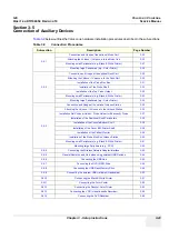
Section 3-5 - Connection of Auxiliary Devices

3-5-1-3

Mounting large Peripherals (e.g., Color Printer)

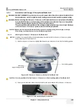
1.) Place the Color Printer, VCR or DVD recorder on the middle peripheral shelf of the Modo Cart.
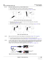
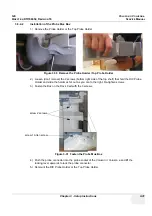
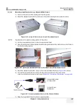
2.) Take a Velcro tape and pull it under the shelf (left image at 

Figure 3-25

 below).  

3.) Pull up the Velcro tape on the front side. The other end of the tape place on the printer 

(right image at 

Figure 3-25

, above).

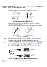
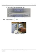
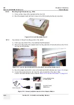
4.) Place the end of the Velcro tape on the top of the other end (left image at 

Figure 3-26

 below).  

NOTE:

Make sure that the Velcro tape is firmly fastened. For reference see: 

Figure 3-21 on page 3-26

.

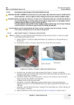
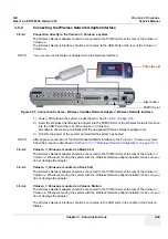
5.) Connect the peripheral device and mount the pull out protection of the power cable.

Links to connection schemes can be found in 

Table 3-9, “Connection Procedures,” on page 3-23

.

NOTE:

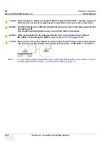
A power extender cable from the power outlets of the Modo Carts isolation transformer should be used 
to connect peripheral devices. Please 

connect the power extender cable to the peripherals first,


then connect the other end to the isolation transformer of the Modo Cart.
(Cables can be routed inside the cable management clips, see: 

Figure 3-11 on page 3-15

.)  

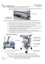
Figure 3-25  pull Velcro tape under shelf and printer

Figure 3-26  fasten Velcro tape

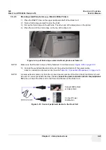
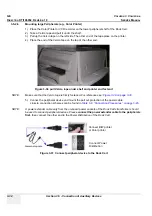
Figure 3-27  Connect peripheral device to the Modo Cart (isolation transformer)

Connect B/W printer
or Color printer

Connect isolation
transformer

General using cable

Summary of Contents for H48651KR

Page 1: ...uson i Voluson e systems with Software version SW 6 x x BT06 Voluson i Voluson e systems with Software version SW 7 x x BT07 Voluson i Voluson e systems with Software version SW 8 x x BT09 11 Voluson i Voluson e systems with Software version SW CC200 BT14 Part Number KTI106052 Revision 10 0123 ...

Page 2: ......

Page 3: ...E L ANGLAIS C EST AU CLIENT QU IL INCOMBE DE LE FAIRE TRADUIRE NE PAS TENTER D INTERVENTION SUR LES ÉQUIPEMENTS TANT QUE LE MANUEL SERVICE N A PAS ÉTÉ CONSULTÉ ET COMPRIS LE NON RESPECT DE CET AVERTISSEMENT PEUT ENTRAÎNER CHEZ LE TECHNICIEN L OPÉRATEUR OU LE PATIENT DES BLESSURES DUES À DES DANGERS ÉLECTRIQUES MÉCANIQUES OU AUTRES DIESES KUNDENDIENST HANDBUCH EXISTIERT NUR IN ENGLISCHER SPRACHE FA...

Page 4: ...E DEVIDO A CHOQUES ELÉTRICOS MECÂNICOS OU OUTROS ESTE MANUAL DE ASSISTÊNCIA ESTÁ DISPONÍVEL APENAS EM INGLÊS SE QUALQUER OUTRO SERVIÇO DE ASSISTÊNCIA TÉCNICA QUE NÃO A GEHC SOLICITAR ESTES MANUAIS NOUTRO IDIOMA É DA RESPONSABILIDADE DO CLIENTE FORNECER OS SERVIÇOS DE TRADUÇÃO NÃO TENTE EFECTUAR REPARAÇÕES NO EQUIPAMENTO SEM TER CONSULTADO E COMPREENDIDO PREVIAMENTE ESTE MANUAL A INOBSERVÂNCIA DEST...

Page 5: ... VAHINGOITTUMINEN SÄHKÖISKUN MEKAANISEN VIAN TAI MUUN VAARATILANTEEN VUOKSI ΤΟ ΠΑΡΟΝ ΕΓΧΕΙΡΙΔΙΟ ΣΕΡΒΙΣ ΔΙΑΤΙΘΕΤΑΙ ΣΤΑ ΑΓΓΛΙΚΑ ΜΟΝΟ ΕΑΝ ΤΟ ΑΤΟΜΟ ΠΑΡΟΧΗΣ ΣΕΡΒΙΣ ΕΝΟΣ ΠΕΛΑΤΗ ΑΠΑΙΤΕΙ ΤΟ ΠΑΡΟΝ ΕΓΧΕΙΡΙΔΙΟ ΣΕ ΓΛΩΣΣΑ ΕΚΤΟΣ ΤΩΝ ΑΓΓΛΙΚΩΝ ΑΠΟΤΕΛΕΙ ΕΥΘΥΝΗ ΤΟΥ ΠΕΛΑΤΗ ΝΑ ΠΑΡΕΧΕΙ ΥΠΗΡΕΣΙΕΣ ΜΕΤΑΦΡΑΣΗΣ ΜΗΝ ΕΠΙΧΕΙΡΗΣΕΤΕ ΤΗΝ ΕΚΤΕΛΕΣΗ ΕΡΓΑΣΙΩΝ ΣΕΡΒΙΣ ΣΤΟΝ ΕΞΟΠΛΙΣΜΟ ΕΚΤΟΣ ΕΑΝ ΕΧΕΤΕ ΣΥΜΒΟΥΛΕΥΤΕΙ ΚΑΙ ΕΧΕΤΕ ΚΑΤΑΝΟΗΣΕΙ ΤΟ...

Page 6: ...YTOVATELE SLUŽEB OBSLUŽNÉHO PERSONÁLU NEBO PACIENTŮ VLIVEM ELEKTRICKÉHOP PROUDU RESPEKTIVE VLIVEM K RIZIKU MECHANICKÉHO POŠKOZENÍ NEBO JINÉMU RIZIKU DENNE SERVICEMANUAL FINDES KUN PÅ ENGELSK HVIS EN KUNDES TEKNIKER HAR BRUG FOR ET ANDET SPROG END ENGELSK ER DET KUNDENS ANSVAR AT SØRGE FOR OVERSÆTTELSE FORSØG IKKE AT SERVICERE UDSTYRET MEDMINDRE DENNE SERVICEMANUAL ER BLEVET LÆST OG FORSTÅET MANGLE...

Page 7: ...ŪTI SUŽEISTAS DĖL ELEKTROS SMŪGIO MECHANINIŲ AR KITŲ PAVOJŲ DENNE SERVICEHÅNDBOKEN FINNES BARE PÅ ENGELSK HVIS KUNDENS SERVICELEVERANDØR TRENGER ET ANNET SPRÅK ER DET KUNDENS ANSVAR Å SØRGE FOR OVERSETTELSE IKKE FORSØK Å REPARERE UTSTYRET UTEN AT DENNE SERVICEHÅNDBOKEN ER LEST OG FORSTÅTT MANGLENDE HENSYN TIL DENNE ADVARSELEN KAN FØRE TIL AT SERVICELEVERANDØREN OPERATØREN ELLER PASIENTEN SKADES PÅ...

Page 8: ...ПЕЦИАЛИСТ ПО ТЕХОБСЛУЖИВАНИЮ ОПЕРАТОР ИЛИ ПАЦИЕНТ ПОЛУЧАТ УДАР ЗЛЕКТРИЧЕСКИМ ТОКОМ МЕХАНИЧЕСКУЮ ТРАВМУ ИЛИ ДРУГОЕ ПОВРЕЖДЕНИЕ ТОВА СЕРВИЗНО РЪКОВОДСТВО Е НАЛИЧНО САМО НА АНГЛИЙСКИ ЕЗИК АКО ДОСТАВЧИКЪТ НА СЕРВИЗНИ УСЛУГИ НА КЛИЕНТ СЕ НУЖДАЕ ОТ ЕЗИК РАЗЛИЧЕН ОТ АНГЛИЙСКИ ЗАДЪЛЖЕНИЕ НА КЛИЕНТА Е ДА ПРЕДОСТАВИ ПРЕВОДАЧЕСКА УСЛУГА НЕ СЕ ОПИТВАЙТЕ ДА ИЗВЪРШВАТЕ СЕРВИЗНО ОБСЛУЖВАНЕ НА ТОВА ОБОРУДВАНЕ ОСВ...

Page 9: ...UZROČENE STRUJNIM UDAROM MEHANIČKIM I DRUGIM OPASNOSTIMA TÁTO SERVISNÁ PRÍRUČKA JE K DISPOZÍCII LEN V ANGLIČTINE AK ZÁKAZNÍKOV POSKYTOVATEĽ SLUŽIEB VYŽADUJE INÝ JAZYK AKO ANGLIČTINU POSKYTNUTIE PREKLADATEĽSKÝCH SLUŽIEB JE ZODPOVEDNOSŤOU ZÁKAZNÍKA NEPOKÚŠAJTE SA VYKONÁVAŤ SERVIS ZARIADENIA SKÔR AKO SI NEPREČÍTATE SERVISNÚ PRÍRUČKU A NEPOROZUMIETE JEJ ZANEDBANIE TOHTO UPOZORNENIA MÔŽE VYÚSTIŤ DO ZRA...

Page 10: ...UN İNGİLİZCE DIŞINDAKİ BİR DİLDE OLMASINI İSTERSE KILAVUZU TERCÜME ETTİRMEK MÜŞTERİNİN SORUMLULUĞUNDADIR SERVİS KILAVUZUNU OKUYUP ANLAMADAN EKİPMANLARA MÜDAHALE ETMEYİNİZ BU UYARININ GÖZ ARDI EDİLMESİ ELEKTRİK ÇARPMASI YA DA MEKANİK VEYA DİĞER TÜRDEN KAZALAR SONUCUNDA TEKNİSYENİN OPERATÖRÜN YA DA HASTANIN YARALANMASINA YOL AÇABİLİR DİKKAT TR JA Traditional Chinese ...

Page 11: ...GE VOLUSON i VOLUSON e DIRECTION KTI106052 REVISION 10 SERVICE MANUAL ix ZH CN KO ...

Page 12: ... comply with the requirements of the applicable electrical codes The purchaser of GE equipment shall only utilize qualified personnel i e GE s field engineers personnel of third party service companies with equivalent training or licensed electricians to perform electrical servicing on the equipment OMISSIONS ERRORS If there are any omissions errors or suggestions for improving this documentation ...

Page 13: ... duplicated in any form in whole or in part without prior written permission of GE GE may revise this publication from time to time without written notice TRADEMARKS All products and their name brands are trademarks of their respective holders COPYRIGHTS All Material Copyright 2006 2013 by General Electric Company Inc All Rights Reserved ...

Page 14: ...te 8a October 04 2010 format issue 9 January 16 2011 Implementation of new parts general update 10 November 06 2013 Implementation of new parts software version CC200 general update Pages Revision Pages Revision Pages Revision Title Page 10 Chapter 3 Setup Instructions pages 3 1 to 3 122 10 Chapter 8 Replacement Procedures pages 8 1 to 8 88 10 Important Precautions pages i to xi 10 Chapter 4 Funct...

Page 15: ... and Icons 1 5 Safety Considerations 1 8 Introduction 1 8 Human Safety 1 8 Mechanical Safety 1 8 Electrical Safety 1 9 Safe Practices 1 9 Probes 1 9 Auxiliary Devices Safety 1 10 Label Location 1 11 Main Label on Voluson i Voluson e system 1 12 Main Label on optional Modo Cart 1 12 Main Label on optional Dock Cart 1 13 Main Label on optional Voluson Station 1 13 Dangerous Procedure Warnings 1 14 V...

Page 16: ...GE VOLUSON i VOLUSON e DIRECTION KTI106052 REVISION 10 SERVICE MANUAL xiv Table of Contents Contact Information 1 18 System Manufacturer 1 18 ...

Page 17: ...Requirements 2 2 EMI Limitations 2 3 Probe Environmental Requirements 2 4 Time and Manpower Requirements 2 4 System Specifications 2 4 Physical Dimensions of Voluson i Voluson e 2 4 Acoustic Noise Output 2 4 Electrical Specifications 2 4 Facility Needs 2 5 Purchaser Responsibilities 2 5 Mandatory Site Requirements 2 6 Site Recommendations 2 6 Recommended Ultrasound Room Layout 2 7 Networking Setup...

Page 18: ...f the Modo Cart 3 15 Front View of the Dock Cart Dock Cart light 3 16 Rear View of the Dock Cart Dock Cart light 3 17 Front View of the Voluson Station 3 18 Rear View of the Voluson Station 3 19 System Voltage Settings 3 20 Modo Cart Voltage Configuration 3 20 Dock Cart Dock Cart light Voluson Station Voltage Configuration 3 21 EMI Protection 3 22 Connection of Auxiliary Devices 3 23 Connection an...

Page 19: ... Hub 3 45 Connection directly to the Voluson i Voluson e system 3 45 Voluson i Voluson e mounted on Modo Cart 3 45 Voluson i Voluson e mounted on Dock Cart 3 45 Voluson i Voluson e mounted on Voluson Station 3 45 Connecting the DVD R RW Drive 3 46 Connection directly to the Voluson i Voluson e system 3 46 Connection via USB hub 3 47 Voluson i Voluson e mounted on Modo Cart 3 47 Voluson i Voluson e...

Page 20: ... 60 Voluson i Voluson e mounted on Modo Cart 3 63 Voluson i Voluson e mounted on Dock Cart 3 63 Voluson i Voluson e mounted on Voluson Station 3 64 Adjustment of the DVD Recorder Settings 3 65 Changing TV System Video format 3 65 Change the Region Code 3 67 Completing the Set Up 3 68 Connecting the Unit to a Power Source 3 68 Voltage Level Checks 3 68 Power On Boot Up 3 69 During a normal boot you...

Page 21: ...djust LCD Brightness 3 101 How to change the Keyboard Layout 3 101 Measure Setup 3 102 Approved Optional Peripherals 3 103 External I O Connectors 3 104 External I O Pin Outs 3 105 External Cables Maximum Lengths 3 106 Available Probes 3 106 Software Option Configuration 3 106 Connectivity Setup 3 107 Connectivity Introduction 3 107 The Dataflow Concept 3 107 Dataflow Examples 3 108 Stand alone Vo...

Page 22: ...CTION KTI106052 REVISION 10 SERVICE MANUAL xx Table of Contents Dicom SonoView Configuration 3 117 Map Network Drive 3 118 Connectivity Setup Worksheet 3 119 Paperwork 3 121 Product Locator Installation 3 121 User Manual s 3 121 ...

Page 23: ...Functions 4 15 Functions after the 3D Acquisition 4 17 Sub Menu 4 19 Using Cine 4 20 Activating Cine 4 20 Cine Split Function Multiple Format 4 20 Activating 2D Auto Cine 4 20 Spectral Doppler or M Cine Loop 4 20 Activating 3D Rotation Cine 4 20 Activating 4D Cine 4 20 Generic Measurements 4 21 Distance and Tissue Depth Measurements 2D and M Mode 4 21 Circumference Area Measurements 4 22 Volume Me...

Page 24: ... and Images 4 28 Save User Settings Only Application Settings 4 29 Load User Settings Only Application Settings 4 30 Preparations 4 30 Load Complete Backup 4 31 Load only parts of the Complete Backup 4 31 Save Full Backup Presets Configurations Application Settings 4 32 Load Full Backup Presets Configurations Application Settings 4 34 Delete Full Backup Presets Configurations Application Settings ...

Page 25: ...rol Description 5 9 B Mode 5 9 Special B Mode Techniques M Mode 5 10 D Mode Pulsed Wave Doppler 5 10 D Mode Autotrace draws PC calculated envelope to D Spectrum 5 11 CFM Mode Color Flow Mode 5 11 3D Mode Freezes after 1 volume sweep 5 11 Real Time 4D Mode nonstop volume rendering 5 11 Sonoview write mode store Image to Sonoview 5 11 Description of Software Options 5 12 3D Mode 5 14 Real Time 4D 5 ...

Page 26: ...face Block 5 23 CardBus Interface 5 23 Bluetooth Module and Antenna 5 23 Wireless Network Adapter 5 23 Wireless Network Interface 5 23 Hard Disk 5 24 Monitoring 5 24 Fan Control 5 25 Temperature Control 5 25 RTC Battery 5 26 Power Management Block 5 26 BackEnd Connectors 5 27 External BackEnd Connectors 5 27 15 LCD Monitor 5 27 Power Supply Unit 5 28 Introduction 5 28 Power Supply Unit Components ...

Page 27: ...42 Introduction 5 42 Recording Tools 5 42 VCR and Video Converter 5 42 DVD Recorder and Video Converter 5 42 Printers 5 42 Black White Digital Printer 5 42 Color Digital Printer 5 42 Color Deskjet Printer 5 42 DVD R W Drive Writer 5 43 Wireless Network Adapter 5 43 Wireless Network Interface 5 43 Footswitch 5 43 External I O 5 43 Air Flow Control 5 44 Air Flow Distribution 5 44 Service Platform 5 ...

Page 28: ...I from external device 5 54 ASI Additional Software Installation 5 54 TCP IP Buffersize 5 54 Activate Deactivate Service 5 54 Common Service Desktop CSD 5 54 Delete all Patients 5 55 Export System Data 5 55 Battery Calibration 5 55 Keyboard Layout 5 55 BootUp Screen 5 55 Monitor Test 5 55 Printer 5 55 Probe EEPROM 5 55 Boot Screen Functions 5 57 Overview 5 57 Voluson 5 57 GE Service 5 57 Rollback ...

Page 29: ...2 LCD Brightness 6 3 Change Color profil 6 4 Network Speed Settings 6 5 Modo Cart Height Adjustment 6 6 Dock Cart Height Adjustment 6 7 Adjusting height of the middle and lower shelf 6 7 Dock Cart light Height Adjustment 6 8 Adjusting height of the shelf 6 8 Voluson Station Height Adjustment 6 9 Modification of Keyboard Layout 6 10 Setup the Voluson i Voluson e Keyboard Language Layout 6 10 Daylig...

Page 30: ...ng the ALT D key 7 9 Export Log s and System Data via Service Page 7 10 Dump file 7 10 Remote Access to Service Platform 7 11 General 7 11 Preparations 7 11 CSD Configuration 7 13 To configure Service Platform 7 13 How to use the Auto Tester program 7 14 Limitation of the Auto Tester 7 16 Minimum Configuration to Boot Scan 7 17 Booting without using the Ultrasound Hardware 7 17 Troubleshooting Tre...

Page 31: ...GE VOLUSON i VOLUSON e DIRECTION KTI106052 REVISION 10 SERVICE MANUAL Table of Contents xxix Error Messages 7 27 ...

Page 32: ...ftware Installation Procedure FMI from external device 8 16 User Settings Only Application Settings Loading Procedure 8 21 Introduction 8 21 Loading Procedure 8 21 Full Backup Presets Configurations Appl Settings Loading Procedure 8 21 Introduction 8 21 Loading Procedure 8 21 Software and Functional Checks after Installation Upgrade Procedure 8 22 Replacement or Activation of Options 8 23 Operatio...

Page 33: ...Procedure 8 28 Handle Installation Procedure 8 28 Replacement of the GPA Battery 8 29 Manpower 8 29 Tools 8 29 Preparations 8 29 Battery Removal Procedure 8 29 Replacement of the Display Front Frame 8 30 Manpower 8 30 Tools 8 30 Preparations 8 30 Display Front Frame Removal Procedure 8 30 Display Front Frame Installation Procedure 8 30 Replacement of the Display Latches right left 8 31 Manpower 8 ...

Page 34: ...he Display Rear Cover 8 38 Manpower 8 38 Tools 8 38 Preparations 8 38 Display Rear Cover Removal Procedure 8 38 Display Rear Cover Installation Procedure 8 39 Replacement of the Modo Cart Components 8 40 Replacement of the Probe Holders 8 40 Manpower 8 40 Tools 8 40 Preparations 8 40 Probe Holder Removal Procedure 8 40 Probe Holder Installation Procedure 8 40 Replacement of the Cable Clips 8 41 Ma...

Page 35: ...cement of the Tray lower 8 47 Manpower 8 47 Tools 8 47 Preparation 8 47 Tray lower Removal Procedure 8 47 Tray lower Installation Procedure 8 47 Replacement of the Cover Bottom 8 48 Manpower 8 48 Tools 8 48 Preparations 8 48 Cover Bottom Removal Procedure 8 48 Cover Bottom Installation Procedure 8 48 Replacement of the Back Column Cover 8 49 Manpower 8 49 Tools 8 49 Preparations 8 49 Back Column C...

Page 36: ...tion Procedure 8 54 Replacement of the Probe Holder for Endocavity probes 8 55 Manpower 8 55 Tools 8 55 Preparations 8 55 Probe Holder Removal Procedure 8 55 Probe Holder Installation Procedure 8 55 Replacement of the Top Probe Holder 8 56 Manpower 8 56 Tools 8 56 Preparations 8 56 Top Probe Holder Removal Procedure 8 56 Top Probe Holder Installation Procedure 8 56 Replacement of the Probe Mux Box...

Page 37: ...s 8 64 Manpower 8 64 Tools 8 64 Preparations 8 64 Probe Holder Removal Procedure 8 64 Probe Holder Installation Procedure 8 64 Replacement of the Additional Shelf Peripherals 8 65 Manpower 8 65 Tools 8 65 Preparations 8 65 Additional Shelf Peripherals Removal Procedure 8 65 Additional Shelf Peripherals Installation Procedure 8 65 Replacement of the Cover BW Printer Shelf 8 66 Manpower 8 66 Tools 8...

Page 38: ...m Cover Installation Procedure 8 72 Replacement of the Top Shelf Bottom Rear Cover 8 73 Manpower 8 73 Tools 8 73 Preparations 8 73 Top Shelf Bottom Rear Cover Removal Procedure 8 73 Top Shelf Bottom Rear Cover Installation Procedure 8 73 Replacement of the Top Column Back Cover 8 74 Manpower 8 74 Tools 8 74 Preparations 8 74 Top Column Back Cover Removal Procedure 8 74 Top Column Back Cover Instal...

Page 39: ...s 8 81 Manpower 8 81 Tools 8 81 Preparations 8 81 Wheels Removal Procedure 8 81 Wheels Installation Procedure 8 81 Replacement of the Back Handle complete 8 82 Manpower 8 82 Tools 8 82 Preparations 8 82 Back Handle Removal Procedure 8 82 Back Handle Installation Procedure 8 82 Replacement of the Power Supply Patient Monitor 8 83 Manpower 8 83 Tools 8 83 Preparations 8 83 Power Supply Patient Monit...

Page 40: ...e of Contents Manpower 8 86 Tools 8 86 Preparations 8 86 VGA Connector Removal Procedure 8 86 VGA Connector Installation Procedure 8 86 Replacement of the DVD Drive 8 87 Manpower 8 87 Tools 8 87 Preparations 8 87 DVD Drive Removal Procedure 8 87 DVD Drive Installation Procedure 8 87 ...

Page 41: ... Covers 9 4 Keyboard parts 9 7 Electronic Parts 9 9 Options and Upgrades 9 15 Miscellaneous Cables 9 20 Optional Peripherals and Accessories 9 26 Recording Tools 9 26 Printers 9 27 Drives additional Devices 9 29 Optional Equipment 9 31 Optional Modo Cart 9 33 Optional Dock Cart Dock Cart light 9 34 Optional Voluson Station 9 38 System Manuals 9 44 Probes 9 50 2D Probes 9 50 Real Time 4D Volume Pro...

Page 42: ... 6 System Checks 10 6 Peripheral Option Checks 10 7 Mains Cable Inspection 10 7 Optional Diagnostic Checks 10 7 Physical Inspection 10 8 Cleaning 10 9 General Cleaning 10 9 Probe Maintenance 10 9 Probe Related Checks 10 9 Basic Probe Care 10 9 Basic Probe Cleaning and or Disinfection 10 10 Disinfection by means of the RIC Holder 10 11 Using a Phantom 10 11 Electrical Safety Tests 10 12 Safety Test...

Page 43: ...ead Source Leakage Lead to Lead 10 21 Lead to Lead Leakage Test Record 10 21 Isolated Patient Lead Sink Leakage Isolation Test 10 22 Isolated Lead sink Leakage Test Record 10 22 Probe Leakage Current Test 10 23 Definition 10 23 Tools 10 23 Generic Procedure on Probe Leakage Current 10 23 When There s Too Much Leakage Current 10 24 Chassis Fails 10 24 Probe Fails 10 24 Peripheral Fails 10 24 Still ...

Page 44: ...GE VOLUSON i VOLUSON e DIRECTION KTI106052 REVISION 10 SERVICE MANUAL xlii Table of Contents ...

Page 45: ...ements 3 Chapter 3 Setup Instructions Contains setup and installation procedures 4 Chapter 4 Functional Checks Contains functional checks that are recommended as part of the installation or as required during servicing and periodic maintenance 5 Chapter 5 Components and Functions Theory Contains block diagrams and functional explanations of the electronics 6 Chapter 6 Service Adjustments Contains ...

Page 46: ...tem History Hardware and Software Versions This manual applies to Voluson i Voluson e systems with Serial Number B00020 B00742 BT06 Voluson i systems with Serial Number B01001 B01494 BT07 Voluson e systems with Serial Number B50001 B50799 BT07 Voluson i systems with Serial Number B02000 B02779 BT09 Voluson e systems with Serial Number B52000 B53200 BT09 Voluson i systems with Serial Number B03001 ...

Page 47: ...e different levels of concern are identified by a flag word that precedes the precautionary message Known or potential hazards are labeled in one of following ways NOTE Notes provide important information about an item or a procedure Information contained in a NOTE can often save you time or effort DANGER DANGER INDICATES THE PRESENCE OF A HAZARD THAT WILL CAUSE SEVERE PERSONAL INJURY OR DEATH IF ...

Page 48: ...e used to make you aware of specific types of hazards that could cause harm Even if a symbol isn t used in this manual it is included for your reference Other hazard icons make you aware of specific procedures that should be followed Table 1 3 Standard Hazard Icons ELECTRICAL MECHANICAL RADIATION LASER HEAT PINCH Table 1 4 Standard Icons Indicating a Special Procedure be Used AVOID STATIC ELECTRIC...

Page 49: ...of each probe Catalog or model number Identification and Rating Plate rear side of the unit on plug of each probe Device Listing Certification Labels Laboratory logo or labels denoting conformance with industry safety standards such as UL or IEC on the base of the unit Main label CE Conformity mark according to Medical Device Directive 93 42 EEC 0123 Identification number of notified body TÜV Süd ...

Page 50: ...sult the accompanying documents operator manual or other instructions rear side of the unit DANGER Risk of explosion used in The system is not designed for use with flammable anesthetic gases Indicated in the Service Manual CAUTION The equilateral triangle is usually used in combination with other symbols to advise or warn the user various ATTENTION Consult accompanying documents This symbol is us...

Page 51: ...he United States of America federal law restricts this device to sale by or on the order of a physician Identification and Rating Plate rear side of the unit GOST R label Russia Regulatory Country Clearance Identification and Rating Plate rear side of the unit These symbols indicate that at least one of the six hazardous substances of the China RoHS Labelling Standard is above the RoHS limitation ...

Page 52: ...ys or diagonally ALWAYS Be sure the pathway is clear Use slow careful motions WARNING WARNING WARNING It is not possible to fix the Voluson i Voluson e on mounting plate of the Cart When the Voluson i Voluson e scanner is used with the Cart make sure the unit is firmly placed in correct position since it may become unstable and tip over WARNING WARNING WARNING Use extreme caution when elevating th...

Page 53: ...e AC DC converter used for this equipment should not be shared with other types of equipment Both the system power cable and the power connector meet international electrical standards 1 3 4 2 Probes All the probes for the Voluson i Voluson e portable ultrasound system are designed and manufactured to provide trouble free reliable service To ensure this correct handling of probes is important and ...

Page 54: ... USB ports other than approved and provided by GE The ultrasound system is an extremely sensitive and complex medical system Any unauthorized peripherals may cause system failure or damage WARNING WARNING WARNING For Ethernet connection a separation device has to be used NOTICE Internally powered applied parts type BF according to IEC60601 1 including national deviations Information for service pe...

Page 55: ...nt with direct main connection requires galvanic separation of the signal and or control leads WARNING WARNING WARNING After each installation the leakage currents have to be measured according to IEC 60601 1 respectively UL 60601 1 see Section 10 7 2 on page 10 13 NOTICE NOTICE When the Voluson i Voluson e scanner is used with the Cart make sure the voltage jumper on the isolation transformer of ...

Page 56: ...ed on the base of the system e g Voluson e 1 Manufacturing date 4 Model type and Serial number 7 CE marking 2 TÜV NRTL Classified 5 WEEE Disposal Icon 8 FDA Guidance document 3 Manufacturer 6 Safety type Type BF 9 GHOST R label Figure 1 3 Main Label located on back of the Modo Cart 1 Model Type 4 Manufacturer 2 Input Output Specification 5 Serial number 3 WEEE Disposal Icon 6 Manufacturing date 7 ...

Page 57: ...el on optional Voluson Station The Main Label is located on the back of the Voluson Station Figure 1 4 Main Label located on back of the Dock Cart 1 Model Type 4 Manufacturer 2 Input Specification 5 Manufacturing date 3 WEEE Disposal Icon Figure 1 5 Main Label located on back of the Voluson Station 1 Model Type 4 Manufacturer 2 Input Specification 5 Manufacturing date 3 WEEE Disposal Icon 1 2 3 4 ...

Page 58: ...earest you NOTE Regulations vary for different countries Dispose of a used battery in accordance with local regulations DANGER DANGER DANGEROUS VOLTAGES CAPABLE OF CAUSING DEATH ARE PRESENT IN THIS EQUIPMENT USE EXTREME CAUTION WHEN HANDLING TESTING AND ADJUSTING WARNING WARNING WARNING EXPLOSION WARNING DO NOT OPERATE THE EQUIPMENT IN AN EXPLOSIVE ATMOSPHERE OPERATION OF ANY ELECTRICAL EQUIPMENT ...

Page 59: ... during use recharging or storage immediately remove it and stop using it If you have any questions about the battery consult your local GE representative Storage of the battery pack Short term less than 1 month between 0 C 32 F and 50 C 122 F Long term more than 3 months between 10 C 50 F and 35 C 95 F For further details refer to Chapter 3 Internal Lithium Ion Battery on page 3 73 NOTE When ship...

Page 60: ...ple body coils or an ultrasound probe The purpose of the regulation is to protect employees in the transportation industry as well as the people who will receive or open this package NOTE The US Department of Transportation DOT has ruled that items what were saturated and or dripping with human blood that are now caked with dried blood or which were used or intended for use in patient care are reg...

Page 61: ...The Voluson i Voluson e unit conforms to all applicable conducted and radiated emission limits and to immunity from electrostatic discharge radiated and conducted RF fields magnetic fields and power line transient requirements as mentioned in IEC 60601 1 2 NOTE For CE Compliance it is critical that all covers screws shielding gaskets mesh clamps are in good condition installed tightly without skew...

Page 62: ...ssistance LOCATION PHONE NUMBER USA GE Medical Systems Ultrasound Service Engineering 9900 Innovation Drive RP 2123 Wauwatosa WI 53226 USA Service On site Service Parts Applications Support 1 800 437 1171 1 800 558 2040 1 800 682 5327 or 1 262 524 5698 Canada 1 800 668 0732 Latin America Service Applications Support 1 800 321 7937 1 262 524 5698 Europe GE Ultraschall Deutschland GmbH Beethovenstra...

Page 63: ...system installation updates and repairs However operator and patient comfort may be optimized if the room light is subdued and indirect Therefore a combination lighting system dim bright is recommended Keep in mind that lighting controls and dimmers can be a source of EMI which could degrade image quality These controls should be selected to minimize possible interference Table 2 1 Contents in Cha...

Page 64: ...o a separate outlet for any range of 100 250 VAC 47 63 Hz 2 2 2 2 Inrush Current Inrush current is not a factor for consideration due to the inrush current limiting properties of the power supplies 2 2 2 3 Site Power Outlets A dedicated AC power outlet must be within reach of the unit without extension cords Other adequate outlets for the external peripherals medical and test equipment needed to s...

Page 65: ...e unit Poor grounding is the most likely reason a unit will have noisy images Check grounding of the power cord and power outlet Replace and or reassemble all screws RF gaskets covers and cores After you finish repairing or updating the system replace all covers and tighten all screws Any cable with an external connection requires a magnet wrap at each end Install the shield over the front of the ...

Page 66: ... 2 2 6 2 Acoustic Noise Output max 45 dB A 2 2 6 3 Electrical Specifications Please refer to Section 2 2 2 1 Voluson i Voluson e Power Requirements on page 2 2 NOTICE NOTICE SYSTEMS AND ELECTRONIC PROBES ARE DESIGNED FOR STORAGE TEMPERATURES OF 10 TO 50 degrees C WHEN EXPOSED TO LARGE TEMPERATURE VARIATIONS THE PRODUCT SHOULD BE KEPT IN ROOM TEMPERATURE FOR 10 HOURS BEFORE USE CAUTION CAUTION Only...

Page 67: ...y utilize qualified personnel to perform electrical servicing on the equipment The desire to use a non listed or customer provided product or to place an approved product further from the system than the interface kit allows presents challenges to the installation team To avoid delays during installation such variances should be made known to the individuals or group performing the installation at...

Page 68: ...case or on a rack Material to safely clean probes performed using a plastic container never metal In the case of a network option An active network outlet in the vicinity of the ultrasound unit A network cable of appropriate length regular Pin to Pin network cable An IT administrator who will assist in configuring the unit to work with your local network A fixed IP address is required Refer to the...

Page 69: ...ltrasound Room Layout Figure 2 1 shows a floor plan illustrating the recommended layout of the Ultrasound Room and depicting the minimal room layout requirements Figure 2 1 Recommended Floor Plan 4 3m x 5 2m 14ft x 17ft 36 IN 92 CM Dedicated Power Outlets Hospital Network Cabinet for Software and Manuals optional VOLUSON i ...

Page 70: ...eripherals enabling viewing to be done while scanning continues With DICOM images can be archived stored and retrieved faster easier and at a lower cost 2 3 4 4 DICOM Option Pre installation Requirements To configure the Voluson i Voluson e ultrasound unit to work with other network connections the network administrator must provide some necessary information Use the Connectivity Setup Worksheet o...

Page 71: ... Cart or Voluson Station optional A worksheet is provided see page 3 119 to page 3 120 to help ensure that all the required information is available prior to setup the system Table 3 1 Contents in Chapter 3 Section Description Page Number 3 1 Overview 3 1 3 2 Set Up Reminders 3 2 3 3 Receiving and Unpacking the Equipment 3 4 3 4 Preparing for Set Up 3 9 3 5 Connection of Auxiliary Devices 3 23 3 6...

Page 72: ...ions occur unplug the power cord Only qualified service personnel should carry out servicing and troubleshooting NOTE For information on shipping carton labels refer to Figure 3 1 on page 3 3 3 2 2 1 System Acclimation Time After being transported the Voluson i Voluson e system may be very cold or hot It requires one hour for each 2 5 C increment if it s temperature is below 10 C or above 40 C Tab...

Page 73: ... properly grounded power outlet Do NOT use a three to two prong adapter This defeats safety grounding CAUTION CAUTION Do NOT wear the ESD wrist strap when you work on live circuits and more than 30 V peak is present CAUTION CAUTION Do not operate this unit unless all board covers and frame panels are securely in place to ensure optimal system performance and cooling When covers are removed EMI may...

Page 74: ...to the system Move the Cart forward or backward when going up or down inclines Do not move the Cart sideways or diagonally Table 3 4 Shipping Cartons Dimensions and Weights Description Height Width Depth Weight Voluson i Voluson e incl peripherals and accessories 75 cm 30 inch 93 cm 37 inch 70 cm 28 inch 50 kg 110 lbs Voluson Modo Cart only 106 cm 41 7 inch 75 cm 29 5 inch 70 cm 28 inch 58 5 kg 12...

Page 75: ...cking material bubble packs foam sections silica gel etc Continue to remove additional packing material as applicable during the following procedure steps 4 Carefully remove the boxes containing the Voluson i Voluson e scanner peripherals probes etc as well as the package containing further accessories e g cables and software CD 5 Before commencing the installation procedure check visual damage Fi...

Page 76: ...g the Modo Cart Continue to remove additional packaging material as applicable during the following procedure steps 5 Using two people carefully roll the Modo Cart down the unloading ramp to remove it completely from the shipping carton Make sure the Modo Cart is standing firmly on the floor before applying the locking brake 6 Before commencing the installation procedure check visual damage CAUTIO...

Page 77: ... Cart Continue to remove additional packaging material as applicable during the following procedure steps 5 Using two people carefully roll the Dock Cart down the unloading ramp to remove it completely from the shipping carton Make sure the Dock Cart is standing firmly on the floor before applying the locking brake 6 Before commencing the installation procedure check visual damage CAUTION CAUTION ...

Page 78: ...g the Voluson Station Continue to remove additional packaging material as applicable during the following procedure steps 5 Using two people carefully roll the Voluson Station down the unloading ramp to remove it completely from the shipping carton Make sure the Voluson Station is standing firmly on the floor before applying the locking brake 6 Before commencing the installation procedure check vi...

Page 79: ...spect the control console for missing or damaged items After switching on the system verify the proper illumination of all the control panel buttons 4 Probes Check all probes for wear and tear on the lens cable and connector Look for bent or damaged pins on the connector and in the connector socket on the unit Verify that the EMI fingers around the probe connector socket housing are intact Check t...

Page 80: ...ks exposed insulation or any deterioration Verify continuity 6 Front Castors Check that the front castors can swivel and can be placed in the locked position by pressing the foot brake lever n each castor 7 Rear Castors Check that the rear castors can roll and swivel 8 Modo Cart Voltage Verify that the voltage of the optional Modo Cart is correct see Section 3 4 3 Modo Cart Voltage Configuration o...

Page 81: ...er and a damp cloth to remove all traces of gel 3 Covers Check that all screws are in place all chassis and internal covers are installed 4 Transformer Check the power supply connectors and the associated cabling for good connection and proper insulation Japan only Exchange pull out protection of main power cord 5 Power Cord Check the power cord for cuts loose hardware tire marks exposed insulatio...

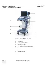
Page 82: ... Front and Side View of the Voluson i Voluson e 1 Display LCD Monitor tilts up and down 2 Speakers two loudspeakers for Doppler sound 3 Control Panel contains TGC slider controls trackball alphanumeric keyboard and different buttons used to operate the Voluson i Voluson e 4 Alphanumeric Keyboard upper row of keys are assigned to ultrasound specific functions 5 Trackball and Trackball buttons 6 Air...

Page 83: ...al accessory connectors Figure 3 9 View of the Voluson i Voluson e Rear Panel 1 Two interchangeable USB ports Printers DVD R RW Drive and other peripherals 2 Docking connector connector for Voluson Station Docking Adapter 3 Port for DC IN AC Adapter 4 SVGA Output VCR option or CRT monitor option 5 LAN 10 100 Base TX Ethernet network connector 6 PCMCIA port for PC card Wireless LAN only available w...

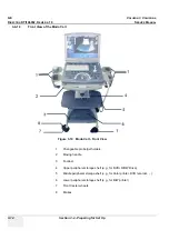
Page 84: ... View of the Modo Cart Figure 3 10 Modo Cart Front View 1 Changeable probe gel holders 2 Moving handle 3 Footrest 4 Upper peripheral storage shelf e g for DVD R RW Drive 5 Middle peripheral storage shelf e g for Color printer DVD recorder 6 Lower peripheral storage shelf e g for B W printer 7 Front Caster wheels 8 Brakes ...

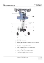
Page 85: ...w 1 Cable hooks 2 Power outlets for Peripherals 3 Isolation Transformer Fuses for changing between 115V and 230V 4 Mains Power Switch 5 Power Cord pull out protection mounted 6 Screws for changing the height of the mounting platform 7 Cable Management clips 8 Voltage Output Selector switch 115V and 230V 9 Place for AC DC Adapter of Voluson i Voluson e 1 2 3 4 5 6 7 8 9 ...

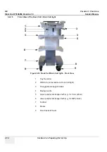
Page 86: ... Dock Cart light Figure 3 12 Dock Cart Dock Cart light Front View 1 Tray Recorder 2 USB Hub not available on Dock Cart light 3 Changeable probe gel holders 4 Moving handle 5 Upper peripheral storage shelf e g for Color printer 6 Lower peripheral storage shelf e g for B W printer 7 Footrest 8 Brakes 9 Front Caster Wheels 3 3 1 2 3 4 6 5 7 9 8 9 ...

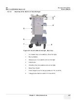
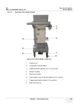
Page 87: ... 3 13 Dock Cart Dock Cart light Rear View 1 Lan Isolation Box not available on Dock Cart light 2 Moving Handles 3 Release Lever not available on Dock Cart light 4 Cable Guide 5 Probe Mux Box not available on Dock Cart light 6 Mains Power Switch 7 Power Supply Fuses for changing between 115V and 230V 8 Voltage Output Selector switch 115V and 230V 1 2 3 4 5 6 7 8 ...

Page 88: ...n 3 4 Preparing for Set Up 3 4 1 7 Front View of the Voluson Station Figure 3 14 Voluson Station Front View 1 Patient Monitor 2 Changeable probe gel holders 3 optional Probe Mux Box 4 Cover BW Printer and Console Bottom Shelf 5 Footrest 6 Brakes 7 Front Caster Wheels 1 2 3 4 5 6 7 7 ...

Page 89: ...luson Station Figure 3 15 Voluson Station Rear View 1 Release Lever 2 Changeable probe gel holders 3 Additional Shelf Peripherals e g for Color printer 4 Storage Tray Back 5 Mains Power Switch 6 Power Supply Fuses for changing between 115V and 230V 7 Voltage Output Selector switch 115V and 230V 8 Back Caster Wheels 1 2 3 4 5 6 7 8 ...

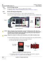
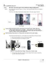
Page 90: ...e fuse protection on the rear of the isolation transformer b Pull out the fuse holder and exchange the 2 fuses c Push the fuse holder back into position correct voltage should be shown in upper line e g 230V see Figure 3 16 above and then close protection CAUTION CAUTION Before starting the system or peripherals connected to the Modo Cart always make sure Rating of isolation transformer fuses is c...

Page 91: ...ply b Pull out the fuse holder and exchange the 2 fuses c Push the fuse holder back into position correct voltage should be shown in upper line e g 230V and then close protection CAUTION CAUTION Before starting the system or peripherals connected to the Cart always make sure Rating of power supply fuses is compatible Output Selector is in correct position The wrong fuses and position of the voltag...

Page 92: ... strong electromagnetic radiation Operate the system in an area enclosed by walls floors and ceilings comprised of wood plaster or concrete which help prevent EMI Shield the system when operating it in the vicinity of radio broadcast equipment if necessary Do not operate mobile phones or other EMI emitting devices in the ultrasound room Verify that all EMI rules listed in the following table are f...

Page 93: ...3 5 3 Connection and Usage of the optional Voluson Station 3 35 Attaching the Voluson i Voluson e to the Voluson Station 3 35 Installation Gel Condom Holder Probe Holder for Endocavity Probe 3 37 Installation of the Additional Shelf Peripherals 3 38 Installation of the Console Bottom Shelf 3 38 Installation of the Cover BW Printer Shelf 3 38 Installation of the Patient Monitor 3 39 Installation of...

Page 94: ...tion requires galvanic separation of the signal and or control leads WARNING WARNING WARNING DO NOT attempt to use different peripherals and accessories other than approved and provided by GE Any unauthorized peripherals may cause system failure or damage WARNING WARNING WARNING After each installation the leakage currents have to be measured according to IEC 60601 1 respectively UL 60601 1 see Se...

Page 95: ... that are connected to the Modo Cart ALWAYS make sure that rating of the isolation transformer fuses is compatible and the voltage output selector is in the correct position The wrong fuses and position of the voltage output selector may cause major damage on the Voluson i Voluson e system and connected peripherals CAUTION CAUTION Make sure that all peripherals are firmly secured in position using...

Page 96: ...nd of the USB cable plug to an USB port on the rear of the Voluson i Voluson e 9 Mount and connect other peripherals as described in Section 3 5 1 2 and Section 3 5 1 3 10 Connect the main power cable to the isolation transformer of the Modo Cart the other end connect to a hospital grade main power outlet with the proper rated voltage 11 Press the Circuit breaker on the Modo Cart To start up the s...

Page 97: ...e Figure 3 21 on page 3 26 5 Connect the peripheral device and mount the pull out protection of the power cable Links to connection schemes can be found in Table 3 9 Connection Procedures on page 3 23 NOTE A power extender cable from the power outlets of the Modo Carts isolation transformer should be used to connect peripheral devices Please connect the power extender cable to the peripherals firs...

Page 98: ...For reference see Figure 3 21 on page 3 26 5 Connect the peripheral device and mount the pull out protection of the power cable Links to connection schemes can be found in Table 3 9 Connection Procedures on page 3 23 NOTE A power extender cable from the power outlets of the Modo Carts isolation transformer should be used to connect peripheral devices Please connect the power extender cable to the ...

Page 99: ...ports LAN cable Connect the ethernet cable routing from the LAN isolation box into the network port of the Voluson i Voluson e 5 Place the DVD Drive on the Tray recorder see Figure 3 10 on page 3 14 and connect it WARNING WARNING WARNING DO NOT CONNECT any devices to any AC power other than the on board outlets from the transformer as this might increase leakage currents and sacrifice patient safe...

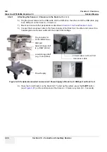
Page 100: ... 5 2 6 8 Connect the main power cable to the Power Supply of the Dock Cart the other end connect to a hospital grade main power outlet with the proper rated voltage 9 Press the Circuit breaker on the Dock Cart To start up the system press the On Off button see Figure 3 87 on the control panel of the Voluson i Voluson e system for 3 seconds Figure 3 29 Peripherals mounted and secured Power Supply o...

Page 101: ... hold the RIC Probe Holder and slide the holder as far out as you can to the right Re tighten screws 3 Fasten the Box on the Dock Cart with the 3 screws 4 Push the probe connector into the probe socket of the Voluson i Voluson e and lift the locking lever upwards to lock the probe connector 5 Remount the RIC Probe Holder or the Top Probe Holder Figure 3 30 Remove the Probe Holder Top Probe Holder ...

Page 102: ...uxiliary Devices 3 5 2 3 Installation of the Probe Shelf 1 Place the Probe shelf and fasten it with the 4 Allen screws 3 5 2 4 Installation of the Top Probe Holder 1 Put the Top Probe Holder into the Top Probe Holder Adaptation Figure 3 32 Fasten the Probe shelf Figure 3 33 Installation Top Probe Holder ...

Page 103: ...astened For reference see Figure 3 29 on page 3 30 5 Connect the peripheral device and mount the pull out protection of the power cable Links to connection schemes can be found in Table 3 9 Connection Procedures on page 3 23 NOTE A power extender cable only from the on board power sockets of the Dock Carts transformer should be used to connect peripheral devices Please connect the power extender c...

Page 104: ...pe is firmly fastened For reference see Figure 3 29 on page 3 30 5 Connect he peripheral device and mount the pull out protection of the power cable Links to connection schemes can be found in Table 3 9 Connection Procedures on page 3 23 NOTE A power extender cable only from the on board power sockets of the Dock Carts transformer should be used to connect peripheral devices Please connect the pow...

Page 105: ...WARNING WARNING WARNING Before starting the Voluson i Voluson e or Peripherals that are connected to the Voluson Station ALWAYS make sure that rating of the power supply fuses is compatible and the voltage output selector is in the correct position The wrong fuses and position of the voltage output selector may cause major damage on the Voluson i Voluson e system and connected peripherals CAUTION ...

Page 106: ...ox enables the connection of up to 3 probes to the Voluson i Voluson e 5 Connect the cable to the rear of the Voluson i Voluson e The cable is listed below LAN cable Connect the ethernet cable routing from the LAN isolation box into the network port of the Voluson i Voluson e 6 Mount and connect other peripherals as described in Section 3 5 3 8 and Section 3 5 3 9 7 Connect the main power cable to...

Page 107: ...he Voluson i Voluson e system for 3 seconds 3 5 3 2 Installation Gel Condom Holder Probe Holder for Endocavity Probe 1 Put the Gel Condom Holder or the Probe Holder for Endocavity Probes into the Holder Adaptation Figure 3 40 Peripherals mounted and secured Power Supply of Voluson Station Figure 3 41 Installation Gel Condom Holder Probe Holder for Endocavity Probes Circuit breaker on Voluson Stati...

Page 108: ...3 5 3 4 Installation of the Console Bottom Shelf 1 Place the Console Bottom Shelf and fasten it with the 2 screws 3 5 3 5 Installation of the Cover BW Printer Shelf 1 Align tab on the front of the Printer Shelf Cover with the slot in front of the Printer Shelf press down and snap into place Figure 3 42 Installation Additional Shelf Peripherals Figure 3 43 Installation Console Bottom Shelf Figure 3...

Page 109: ...rt the right and the left Adapter and fix it with the 2 screws see Figure 3 45 above 3 Fix the tripod with a thumbscrew on the Adapter 4 Fix the head plate from the tripod with a screw on the monitor 5 Connect the VGA Cable to the VGA Connector and connect the Power Cable on the rear of the Voluson Station Figure 3 45 screw out 2 screws Figure 3 46 fix the tripod Figure 3 47 fix the Head Plate ...

Page 110: ...Mux Box Voluson Station 1 Fasten the Probe Mux Box with the 4 screws 2 Push the probe connector into the probe socket of the Voluson i Voluson e and lift the system s locking lever upwards to lock the probe connector NOTE The docking lever cannot be operated if the Probe Box is connected to the Voluson i Voluson e Figure 3 48 Installation Probe Mux Box ...

Page 111: ...er board into the guide slots of the shelf and move the Printer in the final mounting position 5 Mount the adapter board with 1 screw on the Console Bottom Shelf see Figure 3 50 above 6 Connect the peripheral device and mount the pull out protection of the power cable Links to connection schemes can be found in Table 3 9 Connection Procedures on page 3 23 7 Place the Cover BW Printer Shelf at its ...

Page 112: ...4 Place the locking teeth of the adapter board into the guide slots of the shelf and move the VCR in the final mounting position 5 Mount the adapter board with 1 screw on the Additional Shelf Peripherals see Figure 3 53 above 6 Connect the peripheral device and mount the pull out protection of the power cable Links to connection schemes can be found in Table 3 9 Connection Procedures on page 3 23 ...

Page 113: ... the Voluson i Voluson e system follow the procedure described in Section 3 11 1 7 Wireless Network Configuration on page 3 110 3 5 4 2 Voluson i Voluson e mounted on Modo Cart The Wireless Network adapter should be connected to the PCMCIA slot at the rear of the Voluson i Voluson e Whenever moving the system with the Wireless Network adapter installed make sure you do not damage the adapter 3 5 4...

Page 114: ...SB and Network drives connected to the system Using this dialog the USB devices can be stopped before they are physically disconnected To stop the external device select it and then click the STOP DEVICE button Confirm the Stop Device dialog with OK Then CLOSE the Connect USB and Network Drives window see Figure 3 56 above WARNING WARNING Do not connect or disconnect any external USB devices to or...

Page 115: ...d on Dock Cart Not available with the Dock Cart 3 5 6 4 Voluson i Voluson e mounted on Voluson Station Not available with the Voluson Station Figure 3 58 Connection Scheme USB Hub CAUTION CAUTION When connecting directly to the system it is necessary to use additional AC DC power supply supplied with the drive As a safety requirement the AC DC must be medical grade conforming 60601 1 standard or t...

Page 116: ...UTION CAUTION When connecting directly to the system it is necessary to use additional AC DC power supply supplied with the drive As a safety requirement the AC DC must be medical grade conforming 60601 1 standard or the safety must be ensured by the use of a medical grade isolation transformer NOTICE NOTICE Auxiliary equipment with direct mains connection requires galvanic separation e g by use o...

Page 117: ...hould be used to connect the power supply of the DVD R RW drive The DVD R RW can be placed in the upper peripheral storage shelf on the Modo Cart refer to Figure 3 10 on page 3 14 The power cable described above is then plugged into the rear of the DVD device and the data cable is connected to the USB port 3 5 7 4 Voluson i Voluson e mounted on Dock Cart The DVD R RW Drive may be connected to the ...

Page 118: ...Connect to field shows not used see Figure 3 61 above double click the DVD line 3 Click on the arrow icon below the Connect to field and select DVD CD rec from the pop up menu 4 CLOSE the dialog window Figure 3 61 DVD drive not used BT Version BT Version If an external drive was not recognized automatically after connecting it click RESCAN DRIVE only on systems with BT 07 software see Figure 3 56 ...

Page 119: ...dialogs may pop up starting with the Found New Hardware dialog NOTE Memory drives or sticks may be sensitive to EMC interference This may affect system performance and or image quality 3 5 8 2 Connection via USB hub As above If applicable the USB hub must be powered via the isolation transformer 3 5 8 3 Voluson i Voluson e mounted on Modo Cart As above 3 5 8 4 Voluson i Voluson e mounted on Dock C...

Page 120: ...l dialogs may pop up starting with the Found New Hardware dialog NOTE Memory drives or sticks may be sensitive to EMC interference This may affect system performance and or image quality 3 5 9 2 Connection via USB hub As above If applicable the USB hub must be powered via the isolation transformer 3 5 9 3 Voluson i Voluson e mounted on Modo Cart As above 3 5 9 4 Voluson i Voluson e mounted on Dock...

Page 121: ...power cables provided on the Modo Cart 3 5 10 4 Voluson i Voluson e mounted on Dock Cart NOTE For Instructions see Mounting small Peripherals e g Black White Printer on page 3 33 The B W Printer may be connected to the USB ports on the rear of the Voluson i Voluson e The B W Printer must be powered from the Dock Cart itself via one of the isolated peripheral power cables provided on the Dock Cart ...

Page 122: ...Color Printer must be powered from the Modo Cart itself via one of the isolated peripheral power cables provided on the Modo Cart 3 5 11 4 Voluson i Voluson e mounted on Dock Cart NOTE For instructions see Section 3 5 2 6 Mounting large Peripherals e g Color Printer on page 3 34 The Color Printer may be connected to the USB ports on the rear of the Voluson i Voluson e The Color Printer must be pow...

Page 123: ...be connected to an external non isolated power source The bluetooth adapter should be directly connected to the upper USB port on the Voluson i Voluson e rear connectors panel Figure 3 67 HP5940 DeskJet Printer connection via Bluetooth Adapter Figure 3 68 Canon Pixma MP600 MP610 MP550 and HP H470 Printer connection via Bluetooth Adapter Bluetooth Printer Adapter USB Bluetooth Adapter Power Adapter...

Page 124: ...er is also not a medical device The equipment meets the requirements of the EN 60950 Standard CAUTION CAUTION Please observe that the complete Bluetooth Printer Assembly has to be located outside of the patient environment according to IEC 60601 1 UL 60601 1 NOTICE NOTICE Please use the proper Bluetooth Printer Connection set See Chapter 9 Printers on page 9 27 You also can connect the Printer dir...

Page 125: ...hi HS MD3000 VCR PAL and NTSC approved by GE 3 5 13 1 Direct Connection to the Voluson i Voluson e system Use the standard VCR type PAL or NTSC that is suited to your region The video signal is received through a VGA to video converter Figure 3 69 Connection Scheme VCR with Video Scan Converter Canopus power socket Video Converter rear Power Supply Voluson i e rear Isolation Transformer ...

Page 126: ...e rear of the VCR Figure 3 70 Connection Scheme VCR with Video Scan Converter Ophit CAUTION CAUTION When connecting the VCR Video Converter directly to the system it is necessary to use an additional power source As a safety requirement the VCR internal AC DC and the Video Converter AC DC supplied with the Video Converter must be medical grade conforming 60601 1 standard or the safety must be ensu...

Page 127: ...in order to select RGB Input as your signal source The LED located on the video converter front panel will be illuminated accordingly NOTE If the VGA cable is disconnected reconnected while the system is ON the VGA output is maintained NOTE If system is shut down to standby or Full shut down while the VGA device is connected continuously the VGA output will appear after the system is turned ON NOT...

Page 128: ...video converter three times in order to select RGB Input as your signal source The LED located on the video converter front panel will be illuminated accordingly 3 5 13 3 Voluson i Voluson e mounted on Dock Cart NOTE For instructions see Section 3 5 2 6 Mounting large Peripherals e g Color Printer on page 3 34 The VCR must be powered from the Dock Cart itself via one of the isolated peripheral pow...

Page 129: ...ble to AUDIO OUT located on the Image Resizer of the Voluson Station 2 Connect the other end of the Audio cable to AUDIO IN at the rear of the VCR 3 Connect one end of the S Video cable to S VIDEO OUT located on the Image Resizer of the Voluson Station 4 Connect the other end of the S Video cable to S VIDEO IN at the rear of the VCR 5 If not already done set the switch to the correct positions PAL...

Page 130: ...luson e system The video signal is received through a VGA to video converter NOTICE NOTICE The Sony DVO 1000MD DVD recorder is only able to read and write on DVD RW ReWriteable media Please check on your DVD case before using Figure 3 74 Connection Scheme DVD Recorder with Video Scan Converter Canopus power socket power socket isolation transformer Power Supply Video Converter rear Voluson i e rea...

Page 131: ...der Figure 3 75 Connection Scheme DVD Recorder with Video Scan Converter Ophit CAUTION CAUTION When connecting the DVD Recorder Video Converter directly to the system it is necessary to use an additional power source As a safety requirement the DVD Recorder internal AC DC and the Video Converter AC DC supplied with the Video Converter must be medical grade conforming 60601 1 standard or the safety...

Page 132: ...our signal source The LED located on the video converter front panel will be illuminated accordingly 8 Adjust the DVD Recorder settings as described in Section 3 5 14 5 on page 3 65 NOTE If the VGA cable is disconnected reconnected while the system is ON the VGA output is maintained NOTE If system is shut down to standby or Full shut down while the VGA device is connected continuously the VGA outp...

Page 133: ...he LED located on the video converter front panel will be illuminated accordingly 8 Adjust the DVD Recorder settings as described in Section 3 5 14 5 on page 3 65 3 5 14 3 Voluson i Voluson e mounted on Dock Cart NOTE For instructions see Section 3 5 2 6 Mounting large Peripherals e g Color Printer on page 3 34 The DVD recorder must be powered from the Dock Cart itself via one of the isolated peri...

Page 134: ...izer of the Voluson Station 2 Connect the other end of the Audio cable to AUDIO IN at the rear of the DVD recorder 3 Connect one end of the S Video cable to S VIDEO OUT located on the Image Resizer of the Voluson Station 4 Connect the other end of the S Video cable to S VIDEO IN at the rear of the DVD recorder 5 If not already done set the switch to the correct positions PAL or NTSC 6 When all pow...

Page 135: ...ENU button A located on the front of the DVD recorder see Figure 3 79 below 3 The Main Menu appears on the LCD screen of the DVD recorder see Figure 3 80 below 4 Press the down button on the front of the recorder repeatedly until the SETUP MENU item is highlighted NOTE Each time you press the up or down button the highlight cursor moves up down item by item 5 Press the right button The Setup Menu ...

Page 136: ...pressing the down button 10 Press the right button The TV System Sub menu appears 11 Select the appropriate video signal by pressing the up or down button respectively To check the video signal see Table 3 10 TV System and Region Code on page 3 67 12 Press the SET button C The message Now loading appears and the unit starts to save the settings 13 When Power off appears on the display press the PO...

Page 137: ...dly until REGION CODE is highlighted 7 Press the right button The Region Code Menu appears 8 Select the appropriate region code by pressing the up or down button respectively To check the region code see Table 3 10 TV System and Region Code on page 3 67 9 Press the SET button C The message Now loading appears and the unit starts to save the settings 10 When Power off appears on the display press t...

Page 138: ...ive grounding conductor Never use an adapter or converter to connect with a power source plug for example a three prong to two prong converter WARNING WARNING WARNING The unit s power must be supplied from a separate properly rated outlet to avoid risk of fire Refer to Section 2 2 2 1 Voluson i Voluson e Power Requirements on page 2 2 for rating information The power cord should not under any circ...

Page 139: ...able via the AC Adapter to the Power Inlet DC In connector on the rear of the Voluson i Voluson e system see Figure 3 85 CAUTION CAUTION Before starting the Voluson i Voluson e or peripherals that are connected to the Cart always make sure Rating of power supply fuses is compatible Output Selector is in correct position The wrong fuses and position of the voltage output selector may cause major da...

Page 140: ... the operating system Running a quick diagnostic check of the system Detecting connected probe As soon as the software has been loaded the system enters 2D Mode with the probe and application that were used before the system was shut down NOTE Total time used for start up is typically one minute NOTE When turning on the Voluson i Voluson e from Standby mode it takes a few seconds before it respond...

Page 141: ...ps 1 The Boot Screen is displayed Voluson is highlighted Figure 3 88 below 2 Back End Processor is turned ON and starts to load the software 3 The Start Screen Voluson i is displayed on the monitor 4 Start up process bars indicating software loading procedures are displayed on the monitor as shown in Figure 3 89 below 5 The software initiates and sets up the Front End electronics and the rest of t...

Page 142: ...er cable to the main power outlet again as soon as possible and at least before you switch on the main power and press the On Off button Figure 3 90 Shutdown Restart or Standby NOTICE NOTICE The battery is automatically charged when the system is plugged into an active wall outlet It takes approximately 10 hours to charge a flat battery If the system is left in the OFF condition system unplugged f...

Page 143: ...therefore battery fully charged Table 3 11 Battery Status Icon Status Description AC Power is on no battery present AC Power is on battery is full Battery in use battery almost empty Battery in use fully charged Battery in use partly charged AC Power is on battery is charging Figure 3 91 Battery Capacity check NOTICE NOTICE If the system is left in the OFF condition system unplugged from the wall ...

Page 144: ...al authorities for the location of a chemical waste collection program nearest you CAUTION CAUTION To avoid the battery bursting igniting or fumes from the battery causing equipment damage observe the following precautions Do not immerse the battery in water or allow it to get wet Do not put the battery into a microwave oven or pressurized container If the battery leaks or emits an odor remove it ...

Page 145: ...n page 3 73 and the charger will automatically starts charging During the charging procedure the green LED is flashing At the end of this procedure when the battery is fully charged the solid green LED is illuminated in the status window indicating a fully charged battery CAUTION CAUTION Always observe the following SAFETY precautions Do not use in patient environment Do not use in anesthetic and ...

Page 146: ...ecalibration by means of External Battery Charger NOTE For more details on recalibration and an explanation of why it is necessary refer to Section 5 5 6 2 Recalibration on page 5 34 Table 3 12 Battery Charger LED Indicators and Status LED Indicator Status Green Flashing Battery charging Green Solid Battery fully charged Blue flashing Battery in calibration mode Blue Solid Battery fuel gauge calib...

Page 147: ...E page on the screen The password window appears automatically 3 Enter the password SHE and click the ACCEPT button to display the Service Tools window 4 Click on the BATTERY CALIBRATION button 5 Confirm the following dialog with YES 6 Follow the steps as described in the Battery Calibration wizard until Recalibration is finished Figure 3 93 Service Tools window Figure 3 94 Confirm with YES Batter...

Page 148: ...ress the recalibration button part way through the recalibration cycle 1 To recalibrate the battery press the Calibrate button on the front of the battery charger unit NOTE No action is required if only a recharge is required as the charger will automatically begin to charge the battery The blue calibration LED will flash to indicate that the battery is undergoing the recalibration cycle There may...

Page 149: ...lock in place 4 Carefully position the probe cord so that it is free to move and is not resting on the floor NOTE For Connecting a probe to the Dock Cart please refer to 3 on page 29 For Connecting a probe to the Voluson Station please refer to 3 on page 36 NOTE Prior to connecting or disconnecting a probe freeze the image It is not necessary to turn OFF power to connect or disconnect a transducer...

Page 150: ...nter Sony UP D897 on page 3 81 Section 3 7 2 Installing Digital Color Printer Sony UP D23MD or UP D25MD on page 3 83 Section 3 7 3 Installing Mitsubishi B W Printer P95 and Color Printer CP30 on page 3 85 Section 3 7 4 Printer Installation manually on page 3 87 Section 3 7 5 Adjustment of Printer Settings on page 3 91 CAUTION CAUTION The Bluetooth Printer Connection set as well as the Color Deskje...

Page 151: ...ed NOTE The power switch of the printer has to be in ON position before starting the system 3 7 1 1 Install the UP D897 printer software driver Perform the following steps if this printer was never installed on the Voluson i Voluson e 1 Connect the USB cable to the printer and the system The windows Searching for Drivers Found new Hardware and finally the following windows appear 2 Select No not t...

Page 152: ...essary files are copied 6 If the following Warning message appears click CONTINUE ANYWAY 7 Confirm the installation by clicking FINISH to close the Hardware Wizard 8 Close all open windows and restart the system turn off and on the system Figure 3 98 Search for Network path Figure 3 99 Finish installation NOTICE NOTICE After boot up of the system verify the correct settings in the printer Properti...

Page 153: ...NOTE The power switch of the printer has to be in ON position before starting the system 3 7 2 1 Install the UP D23MD UP D25MD printer software driver Perform the following steps if this printer was never installed on the Voluson i Voluson e 1 Connect the USB cable to the printer and the system The windows Searching for Drivers Found new Hardware and finally the following windows appear 2 Select N...

Page 154: ...necessary files are copied 6 If the following Warning message appears click CONTINUE ANYWAY 7 Confirm the installation by clicking FINISH to close the Hardware Wizard 8 Close all open windows and restart the system turn off and on the system Figure 3 101 Search for Network path Figure 3 102 Finish installation NOTICE NOTICE After boot up of the system verify the correct settings in the printer Pro...

Page 155: ...e when connecting it to the system The printer driver will have to be installed again via hardware wizard Please be sure to leave the printer driver disk at the customer site with the other current software discs NOTE Dip Switch Settings for the Color Printer KTZ302616 1 and 2 ON 3 4 5 6 7 and 8 OFF NOTE If you use the B W Printer KTZ302617 you must first activate USB Serial number 1 The Printer m...

Page 156: ...ver Win2000_XP for the Color Printer Path depeD95 or F Win2000_XP where F stands for CD DVD Drive Then click on NEXT NOTE If the Printer Driver Disk is defective or not available download driver from GE folders http libraries ge com foldersIndex do entity_id 15869258101 sid 101 SF 1 15869248101 and extract files to CD or USB disk 6 Confirm the installation by clicking FINISH to close the Hardware ...

Page 157: ...ord window appears automatically 4 Enter the password SHE and click the ACCEPT button to display the Service Tools window 5 Click on the PRINTER button 6 Click the ADD PRINTER button A warning message appears Please read this message carefully and click YES if you have skills to do this Click the NEXT button to start the Add Printer Wizard Figure 3 106 Service Tools window Figure 3 107 Add Printer...

Page 158: ...lation manually cont d 7 Select the Local Printer deselect Automatically install Plug and Play printer and then click NEXT 8 Select the corresponding Printer Port e g Figure 3 109 USB001 and click NEXT 9 In the following window select the HAVE DISK button Figure 3 108 Add Printer Wizard Figure 3 109 Select Printer Port Have Disk ...

Page 159: ...in 12 Verify the selected Printer Driver path and confirm with OK 13 Select the manufacturer and model of your printer and confirm with the NEXT button 14 Assign a name decide if printer should be used as default printer and confirm with NEXT NOTE If the Printer Sharing window appears select Do not share this printer and confirm with NEXT Figure 3 110 Select Printer Driver path R system periph ver...

Page 160: ...ith the FINISH button NOTE If the message The software you are installing for this hardware has not passed Windows appears click CONTINUE ANYWAY 17 Close all open windows close the System Setup with SAVE EXIT and restart the system turn off and on the system Figure 3 112 Complete manual Printer Installation NOTICE NOTICE After boot up of the system verify the correct settings in the printer Proper...

Page 161: ...enu and click the EDIT SETTINGS button 6 Confirm the warning message with the YES button The Printer Properties appear To adjust the UP D897 Printer see Section 3 7 5 1 UP D897 Printer Settings To adjust the UP D23MD Printer see Section 3 7 5 2 UP D23MD UP D25MD Printer Settings To adjust the Mitsubishi Printer see Section 3 7 5 3 Mitsubishi Printer Settings To adjust the Bluetooth Printer see Sec...

Page 162: ...Orientation Portrait Interpolation Method Bilinear 3 Select the DENSITY ADJUST page see Figure 3 114 above and select Gamma TONE2 Sharpness 0 Dark 0 Light 0 Sharpness 2 4 For saving the adjusted printer settings click APPLY and then OK Finally close the Printers window with the close button and exit System Setup with SAVE EXIT 5 Assign the Printer to the remote keys P1 P2 and or P3 see Section 3 7...

Page 163: ...7 5 Adjustment of Printer Settings 2 Select the PAPER page and select Paper Size UPC 23L large UPC 23S small Orientation Landscape recommended when using large paper size High Speed check mark on NOTICE NOTICE Settings for Paper Size MUST match with the used Paper large small and also the right color ink cartridge has to be used Otherwise you will get an error message at printing Figure 3 115 Pape...

Page 164: ... Balance Cyan 0 Magenta 0 Yellow 0 b Gamma Select Gamma 1 c Color Correction set Printer Hardware Color Correction d Lightness Sharpness 7 or 8 Dark 0 Gamma 12 Light 8 4 For saving the adjusted printer settings click APPLY and then OK Finally close the Printers window with the close button and exit System Setup with SAVE EXIT Figure 3 116 Graphics page Color Balance Gamma Select Figure 3 117 Graph...

Page 165: ...tton and exit System Setup with SAVE EXIT 3 7 5 3 2 B W Printer P95 1 Printer Settings directly on the B W Printer a Press the BRT button on the printer and adjust Brightness to 0 by using the turning knob b Press the CONT button on the printer and adjust Contrast to 0 by using the turning knob c Press the SHARP button on the printer and adjust Sharpness to 3 by using the turning knob d Press the ...

Page 166: ...tings click APPLY and then OK 5 In the next window click OK again Finally close the Printers window with the close button and exit System Setup with SAVE EXIT 6 Assign the Deskjet printer as Report Printer see Section 3 7 6 Printer Remote Control Selection on page 3 97 7 Print report page s containing measurements For operation see Basic User Manual of Voluson i Voluson e 8 Turn off the system CAU...

Page 167: ...ct the P1 P2 P3 page If not currently shown select the Print tab Configure Remote Buttons Select the desired remote control button Select Printer Select the desired Printer for the selected remote control button If it is desired check mark For Reports use Report Printer Report Printer all Buttons Select the desired Report Printer from the drop down menu Figure 3 121 P1 P2 P3 page Print tab NOTICE ...

Page 168: ...onoview and Network configuration nodes System Info shows which Software Hardware version is installed in the system To invoke the Setup procedure In general operations are done with the trackball and the trackball keys mouse emulation NOTICE NOTICE More detailed information pertaining System Setup adjustments is found in Voluson i Voluson e Basic User Manual see Table 9 26 System Manuals Voluson ...

Page 169: ...Dates on page 6 12 3 8 1 2 How to enter Hospital Name Select the GENERAL page in the System Setup see Figure 3 122 1 Select the text box to enter a new Clinic Name with the keyboard 2 Click SAVE EXIT to save Settings and exit System Setup The clinic name will be copied into the Hospital ID in the information header 3 8 1 3 How to change Language and or EUM Language Select the GENERAL page in the S...

Page 170: ...ow to adjust function of the Footswitch Left Right NOTE The Footswitch is available with Software 7 x x and higher Select the USER SETTINGS page in the System Setup 1 Select desired function of the Footswitch Left and Right 2 Click SAVE EXIT to save Settings and exit System Setup Figure 3 123 System Setup User Settings ...

Page 171: ... 9 or c Retype new Password and then click SAVE EXIT to save new screen lock password 2 Click SAVE EXIT to save Settings and exit System Setup Status of the Screen Lock is shown in the menu area of the Utilities menu I 3 8 1 6 How to adjust LCD Brightness see Chapter 6 LCD Brightness on page 6 3 3 8 1 7 How to change the Keyboard Layout see Chapter 6 Setup the Voluson i Voluson e Keyboard Language...

Page 172: ...re In general operations are done with the trackball and the trackball keys mouse emulation NOTICE NOTICE Parameters and possible adjustments mostly depend on the selected Application NOTICE NOTICE More detailed information pertaining System Setup adjustments is found in Voluson i Voluson e Basic User Manual see Table 9 26 System Manuals Voluson i on page 9 44 and Table 9 27 System Manuals Voluson...

Page 173: ...0 Video Cassette Recorder Mitsubishi HS MD3000U NTSC HS MD3000E PAL via VGA to S Video converter DVD Recorder SONY DVO 1000MD PAL NTSC via VGA to S Video converter Video Scan Converter Canopus TwinPact 100 VGA port Ophit UVC S100 A USB Hub D Link DUB H7 USB Port DVD R RW Drive Addonics AEPMRRWII88 USB Port Samsung SE T084 USB Port De Lock SE T084 USB Port Teac DV W28U USB Port USB Flash Memory dev...

Page 174: ... USB 2 0 ports Printers DVD R RW drive and other peripheral 2 Docking connector Connector for Voluson Station Docking Adapter 3 Port for DC IN Connector for AC Adapter 4 VGA OUT Table 3 16 print out VGA signal VCR option via VGA to S Video converter 5 NETWORK Table 3 17 twisted pair RJ 45 10 100 megabit s LAN Base TX Ethernet network connector DICOM input output 6 PCMCIA port only available at GPC...

Page 175: ...n 1 VCC USB Power Supply 2 Data USB Data 3 Data USB Data 4 GND USB Power Ground Table 3 16 VGA OUT Connector Sub D 15 Pin Pin No Output Signal Description 1 VGA OUT1 R Red 2 VGA OUT1 G Green 3 VGA OUT1 B Blue 4 9 11 12 15 N C N C 5 6 7 8 10 GND GND 13 VGA OUT1 HS H Sync 14 VGA OUT1 VS V Sync Table 3 17 Network Connector RJ45 Modular 8 Pin Pin No Output Signal Description 1 ETHER TD Ethernet RD 2 E...

Page 176: ...luson e Basic User Manual Chapter 16 3 2 System Setup User Settings For information on configuring assignment of the P1 P2 and P3 keys refer to the Voluson i Voluson e Basic User Manual Chapter 16 3 3 System Setup P1 P2 P3 For information on configuring Connectivity refer to the Voluson i Voluson e Basic User Manual Chapter 16 3 7 System Setup Network For information on configuring settings and pa...

Page 177: ... A Voluson i Voluson e and a DICOM server in a network see Section 3 11 1 5 on page 3 109 A Voluson i Voluson e used in conjunction with a Voluson Station with its own built in NIC see Section 3 11 1 6 on page 3 109 3 11 1 1 The Dataflow Concept Communication between the Voluson i Voluson e ultrasound unit and other information providers on the network takes the form of data flows Each dataflow de...

Page 178: ... View Voluson i e The local database is used for patient archiving Images are stored to internal hard drive The local database is used for patient archiving Images are stored to a DVD CD Search in the DICOM Modality Worklist the patient found is copied into local database The patient information and the examination results are stored to the local database Images are stored to a DICOM server and to...

Page 179: ...t saved on the local image buffer on the scanner At the end of the examination the images are sent to the DICOM server via a DICOM spooler This scenario requires that the scanner is configured to be connected to the DICOM server Physical Connection You will need one network cable 1 Connect one end of the cable to the Ethernet connector on the Voluson i Voluson e 2 Connect the other end of the cabl...

Page 180: ...ilities menu 3 Select SYSTEM and then open the NETWORK page on the System Setup desktop screen 4 Click the WLAN CONFIGURATION button The CURRENT STATUS of the selected Profile is displayed as shown in Figure 3 129 below NOTICE NOTICE To configure the Voluson i Voluson e ultrasound unit to work with the WLAN adapter WLAN Interface the hospital s network administrator must provide the required infor...

Page 181: ...le or MODIFY an existing profile the Profile Management windows appear e g Figure 3 131 Profile Management General on page 3 112 Each of these windows listed below enable you to set the configuration parameters for that profile Figure 3 130 Profile Management General Prepares the client adapter for use in a wireless network Advanced Controls how the client adapter operates within an infrastructure...

Page 182: ...y but can be changed Note Each computer on the network should have a unique client name SSID1 The service set identifier SSID identifies the specific wireless network that you want the client adapter to access Type the Network Name as provided to you by the hospital s Network Administrator Note If you leave this parameter blank your client adapter can associate to any access point on the network t...

Page 183: ...e time Consumes the most power but offers the highest throughput Is recommended for desktop computers and devices that use AC power Fast PSP Power Save Mode Switches between PSP and CAM mode depending on network traffic Is recommended when power consumption is a concern but you need greater throughput than that allowed by Max PSP Max PSP Max Power Saving Conserves the most power but offers the low...

Page 184: ...hich your client adapter should transmit packets to or receive packets from access points Default All options selected Note When more than one option is selected the client adapter attempts to use the wireless modes in this order 5 GHz 54 Mbps 2 4 GHz 54 Mbps 2 4 GHz 11 Mbps Note Your client adapter s wireless mode must match that of the access points with which it is to communicate Otherwise your...

Page 185: ...verytime Click the NEW button to set up a new profile Specify a name for the Network Profile in the Profile Name textfield There are two options Current Settings The current Network Setup of the system is stored in the Network Profile The dropdown field lists all stored Network Profiles Choose this option and the desired source profile to copy the settings to the new profile Click OK to save the N...

Page 186: ... Network Configuration 1 Press the UTILITIES key on the keyboard once to display the Utilities menu 2 Select SYSTEM and then open the NETWORK page on the System Setup desktop screen 3 Click the NETWORK CONFIGURATION button read the message and confirm with YES 4 The Internet Protocol TCP IP Properties dialog page appears To specify a DICOM Address follow the instructions in the Basic User Manual o...

Page 187: ...tion between medical devices on the network Using the DICOM option you can send or print images after connecting your ultrasound equipment and PACS This dialog section is used to set up details of all of your DICOM target nodes image servers Once you have set up a DICOM node properly data can simply be transmitted by selecting the appropriate target node For more information follow the instruction...

Page 188: ... the connection to the remote machine If successful the DISCONNECT button becomes active Press the USB key on the keyboard the Connect USB and Network Drives dialog window see Figure 3 56 on page 3 44 is displayed Figure 3 139 Map Network Drive window NOTICE NOTICE If there is an error during the connection a warning message appears inside the dialog In this case please verify the data in the dial...

Page 189: ...ation Services Destination Devices TCP IP Settings Device Type Manufacturer Name IP Address Port AE Title 1 2 3 4 5 6 7 8 9 10 11 12 Dept Voluson i eSN Type Floor Room REV Comments CONTACT INFORMATION Name Title Phone E Mail Address Site System IP Settings IP Address Subnet Mask Default Gateway Server Name Remote DB User Name Name AE Title Remote Archive Setup IP Address Subnet Mask Default Gatewa...

Page 190: ...1 Worksheet for DICOM Network Information Voluson i Voluson e Host Name AE Title Local Port IP Address Net Mask ROUTING INFORMATION ROUTER2 ROUTER3 ROUTER1 Destination IP Addresses GATEWAY IP Addresses Default DICOM APPLICATION INFORMATION NAME Store 2 Store 3D_1 Store 1 MAKE REVISION IP ADDRESSES PORT AE TITLE Print Worklist Store 3D_2 Storage Commit MPPS Structured Reporting ...

Page 191: ...t safety and user information is available during the operation and service of the complete system 3 14 1 Product Locator Installation NOTE The Product Locator Installation Card shown may not be same as the provided Product Locator card 3 14 2 User Manual s Check that the correct User Manual s for the system and software revision is included with the installation Specific language versions of the ...

Page 192: ...GE VOLUSON i VOLUSON e DIRECTION KTI106052 REVISION 10 SERVICE MANUAL 3 122 Section 3 14 Paperwork This page was intentionally left blank ...

Page 193: ...uired Equipment 4 1 4 3 General Procedure 4 1 4 4 Functional Checks 4 5 4 5 Backup and Restore Database Preset Configurations and Images 4 28 4 6 Software Configuration Checks 4 38 4 7 Peripheral Checks 4 39 4 8 Site Log 4 40 NOTICE NOTICE Most of the information pertaining to this Functional Checks chapter is found in the Voluson i Voluson e Basic User Manual Table 9 26 System Manuals Voluson i o...

Page 194: ...Switch 2 alphanumeric keyboard with main function keys e g Utilities Bodymarks Power up down etc 11 TGC Slider Controls 3 Mode keys 12 Gain key for Active mode 4 Patient Data Entry key 13 Inter memory keys to print save to Sonoview or send to DICOM server 5 Image Management Sonoview key 14 Freeze Run key 6 Patient Report key 15 Trackball and Trackball keys 7 Measurement keys 8 Exit key 9 Menu Poin...

Page 195: ...he status area by their location their function and their actual value of setting They are easily controlled by moving the trackball pressing the trackball keys or switching the corresponding Soft menu button FUNCTION KEYS located on the alphanumeric Keyboard Many main functions e g Utilities Bodymarks Power up down etc are activated by pressing its specific key on the alphanumeric keyboard KEYBOA...

Page 196: ...l Age 16 Status area indicates current operation state 4 Probe Application 17 Status area of Battery Docking icon Remote Service icon and P1 P2 and P3 keys 5 Depth Frame rate 18 Status area of Soft menu buttons 6 Mechanical Index 19 Status area of the trackball and trackball keys 7 Thermal Index 20 Menu Softkey area 8 Sonographers Name 21 Bodymarks 9 Hospital Name Identification 22 Depth scale mar...

Page 197: ...upon system configuration If any Modes or Options are not part of the system configuration the check can be omitted NOTE Different menus are displayed depending on which Menu and which Mode is selected Some function only appear in the menu area and the status area of the Trackball the Trackball keys and the Soft menu buttons if they are available for the selected probe BT Version BT Version The op...

Page 198: ...ode from Single to DUAL or QUAD display mode Press the SINGLE format key or the 2D MODE key to change from Dual or Quad to Single display 5 Image Orientation left right up down Use these keys on the control panel to alternate the image orientation The orientation marker on the screen shows the actual orientation 6 2D Automatic Optimization Pressing the AUTO key causes automatic optimization of the...

Page 199: ...aging function in 2D Mode provided the active probe allows this function 15 ANGLE Press the Soft menu buttons to select a part of interest of the 2D image The advantage of the decreased field of view is an increased 2D frame rate due to the smaller sector width 16 FOC DEPTH Press the Soft menu buttons to select the depth position of the actual focus zone s Arrows at the left edge of the 2D image m...

Page 200: ...improves the detail lateral resolution and signal to noise ratio 27 GRAY MAP A gray map determines the displayed Brightness of an echo in relationship to its amplitude 28 CHROMA This defines the relation between echo amplitude input and Chroma value color tone and saturation in a look up table 29 EXIT Press the EXIT key on the control panel to exit the 2D Sub menu 30 XTD VIEW BT Version BT Version...

Page 201: ...e trace from up to down in the M mode display area The Invert function is only available with endovaginal probes 6 SPEED Press the Soft menu buttons to select different sweep speeds 7 FREQ Common with 2D Mode Freq Resol Harm Freq in case of Harm Imaging 8 ENHANCE Due to this function a finer sharper impression of the image is produced 9 REJECT It determines the amplitude level below which echoes a...

Page 202: ...Checks 4 4 2 1 MCFM Mode Check For further details refer to the Voluson i Voluson e Basic User Manual By pressing the M control and the CFM control the MCFM mode is switched on in preparation mode The M cursor with M Color window appears in the active 2D image Figure 4 6 MCFM Main and MCFM Sub Menu ...

Page 203: ...ring Press the STEERING STEERING key on the alphanumeric keyboard This function is only possible with linear probes 5 RTT Real Time Auto Trace The envelope curve of the Doppler spectrum maximum velocities and the corresponding evaluations are automatically displayed on the monitor 6 Doppler Spectrum Invert Press the DOP INV key on the control panel to invert the Doppler spectrum display in relatio...

Page 204: ...ed transmit frequency for actual gate position 14 DYNAMIC Dynamic Range adjusts the display cutoff of the Doppler analysis waveform 15 FORMAT For selection of either one of three formats 16 SCALE To select the displayed measuring unit in relation to the zero line 17 GRAY MAP A gray map determines the displayed Brightness of an echo in relationship to its amplitude 18 CHROMA This defines the relati...

Page 205: ...ition to Box size 2 Color PD HD Doppler Gain Rotate the ACTIVE MODE rotary control to adjust the Color PD or HD Gain 3 Steering Press the STEERING STEERING key on the alphanumeric keyboard This function is only possible with linear probes 4 2D 2D COLOR PD HD Changes the Single image display to two simultaneous half images The left frame shows only the 2D Mode image The right frame shows the 2D Mod...

Page 206: ...ENCY It serves for selection of the Transmit Frequency which also depends on the Color Box position 17 LINE DENS Determines the line density within the Color Box The lower the line density the larger the line distance and the size of the color pixels 18 LINE FILTER With Line Filter the signals of the neighboring pulses are less weighted for the display of the actual pulse which considerably improv...

Page 207: ...licable at Voluson i systems with BT 09 software BT Version BT Version The options SonoAVC and SonoVCAD labor are only applicable at Voluson i Voluson e systems with BT 09 software NOTICE NOTICE Not all Options are available on the Voluson e marked with in this manual BT Version BT Version The options SonoRS and SonoNT are only applicable at Voluson i Voluson e systems with BT 11 software Figure 4...

Page 208: ...the 4 Chamber view of the heart to a set diagram the system will generate views of LVOT RVOT Stomach IVC SVC and Ductal arch This feature is only available at Voluson i systems with BT 09 software 9 SONOVCAD LABOR BT Version BT Version This Feature allows for supervision of labor using specific measurements aided by onscreen orientation marks This feature is only available at Voluson i Voluson e s...

Page 209: ...t or left trackball key The chosen reference image is marked by the green letter on the screen Note All control functions are automatically assigned to the image chosen for reference 2 Move the image Image data can be moved around 3 Rotation about X axis If not currently active press the MENU POINTER Cursor key near the trackball Now move the cursor to this icon on the screen and then press SET ri...

Page 210: ...thogonal sections A B and C are complied to a 3D section aspect The aspect shows quasi a spatial cut into the reference image 11 VOCAL VOCAL is the combination of 3D ultrasound tissue presented as voxels and the geometric information of surfaces in a 3D data set The main contour axis should lie in the center of the 3D lesion The 3D object should be centered with respect to the rotation axis 12 MIX...

Page 211: ...oma value color tone and saturation of the Sectional Plane Images 6 CHROMA 3D To change the Chroma value color tone and saturation of the rendered 3D image 7 IMAGE INFO On Off switch to show full or reduced Image Info parameter on screen 8 COLOR HIDE On Off switch to show an acquired 3D Color Doppler or 3D Power Doppler image with or without the color information 9 SRI Speckle Reduction Imaging SR...

Page 212: ...lect the END IMAGE of the sequence The selected image is displayed 4 Select the review SPEED and the read ZOOM factor 5 Select the Cine Mode review direction 6 To start stop the Cine Loop playback press the RIGHT OR LEFT TRACKBALL KEY After stopping the sequence move the TRACKBALL to display the images one by one 4 4 6 4 Spectral Doppler or M Cine Loop Press FREEZE then roll the TRACKBALL to displ...

Page 213: ...he control from one cursor to the other press CHANGE the upper trackball key To re adjust a traced line press UNDO the upper trackball key repeatedly General remarks to perform Generic Measurements By pressing the CALIPER key on the control panel the Generic Measurement function is switched on Selection of the desired measurement marks is done with the MENU POINTER Cursor key and the trackball or ...

Page 214: ...the keyboard The original caliper is displayed to restart the measurement To exit the measurement function press the CALIPER key or EXIT key on the control panel 4 4 7 3 Volume Measurements 1 Press the CALIPER key and then select the GENERIC VOLUME in the menu area 2 Select the appropriate item 3 Perform the measurement s using the TRACKBALL and SET right or left trackball key For further details ...

Page 215: ...velope curve requires a clear and low noise record of the Doppler spectrum Otherwise the reliability of the displayed measurement results may not be ensured 4 4 7 4 2 Manual Trace 1 Press the CALIPER key 2 Select the MANUAL TRACE item from the menu area A cursor appears on the screen 3 Move the cursor with the TRACKBALL to the start point of the measurement and press SET right or left trackball ke...

Page 216: ...ng keyboard shortcuts If the MENU POINTER Cursor key nearby the trackball is illuminated the trackball is consequently assigned to select the menu items in the menu area on the left side of the screen Positioning of measurement marks is done with the TRACKBALL Entering and storage of measuring marks is done with SET right or left trackball key To change measuring marks before completion press CHAN...

Page 217: ...l of Voluson i Voluson e for complete cleaning instructions 3 Carefully slide the probe around the right side of the keyboard toward the probe holder Ensure that the probe is placed gently in the probe holder 4 4 9 4 Disconnecting the probe Prior to disconnecting a probe freeze the image It is unnecessary to switch the unit off 1 Press the locking lever downwards to unlock it 2 Carefully slide the...

Page 218: ...ng Exams Printing Exams Images Export Exams Images Backup Exams Restore the Backup Exams DICOM Print Send Verifying and Pinging a Device Sending Images via e mail Browsing and Managing an Exam s stored Image Connectivity and Dataflow Concept and Creation Configuring Connectivity Services Destinations Input of comments and voice annotations Measure Distance and Ellipse Buttons Views DVD CD R W Eras...

Page 219: ...Write Speed of the DVD CD Recorder 1 Click the SETTINGS icon on the left side of the Sonoview screen 2 Select DVD CD RECORDER from the tool bar 3 Choose the Write Speed from the corresponding pop up menu To erase the backup media DVD CD RW press the ARCHIVE key on the Control panel The Sonoview screen appears on the monitor see Figure 4 13 on page 4 26 Figure 4 14 External Devices tab NOTICE NOTIC...

Page 220: ... Save Full Backup Presets Configurations Application Settings on page 4 32 Section 4 5 4 Load Full Backup Presets Configurations Application Settings on page 4 34 Section 4 5 5 Delete Full Backup Presets Configurations Application Settings on page 4 36 The User Settings and or Full Backup can be saved to the following destinations D partition of internal hard disk DVD CD R W Mapped Network Drive Z...

Page 221: ... key on the keyboard The menu area changes to the Utilities menu 3 Select the SYSTEM item from the menu area to activate the setup desktop screen 4 Select the BACKUP page 5 Click the SAVE button of the User Settings Only group 6 Choose the media and click the SAVE button 7 Select the NEW FILE key and enter a file name without extension 8 Click the OK key to start the process When the saving has be...

Page 222: ...page and click the LOAD button of the User Settings Only group 5 Choose the media and click the LOAD key 6 Select the appropriate file and click OK The Load Backup Data window appears CAUTION CAUTION The loading procedure overwrites the existing application settings on the local hard drive Make sure to insert the correct DVD CD Additionally you can load the backup from D User Settings Figure 4 19 ...

Page 223: ...oad Data field 3 Click the LOAD button to start the loading procedure of the complete backup into the system 4 5 2 3 Load only parts of the Complete Backup NOTE Following procedure is required if the user prefers to keep his old setting but new presets have to be added to match the installed Application Software version e g User Programs and 3D 4D Programs for new probe etc 1 Perform Preparations ...

Page 224: ...ystem data NOTE Always Full Backup any presets configurations and application settings to HDD and or DVD before upgrading the software and or application settings This ensures that if the presets need to be reloaded will be the same ones the customer was using prior to service 1 Press the UTILITIES key on the keyboard The menu area changes to the Utilities menu 2 Select the SYSTEM item from the me...

Page 225: ...irectory structure of full backup data Figure 4 24 Other drive drop down menu NOTICE NOTICE When the backup is saved to an external USB device the system has to be informed about the removal of the hardware For this purpose every last dialog of Full Backup Save and Full Backup Delete has a STOP USB DEVICES button see Figure 4 25 Figure 4 25 Please stop USB Devices before unplugging The sub folders...

Page 226: ... sub menu parameters naming will NOT be affected CAUTION CAUTION There are circumstances where it is not possible to load restore all the data The following rules specify the restrictions 1 Generally only restoring data from an older to a newer software version is possible Loading a backup into a system that has a lower software version than the system the backup was created on is prohibited 2 Opt...

Page 227: ... screen 3 Select the BACKUP page and click the LOAD button of the Full Backup group 4 Choose the Destination 5 Click on the backup to be restored additional information is displayed in the table 6 Select the NEXT button The following window will be displayed 7 Select the data to be restored to the Voluson i Voluson e system NOTE For description of the check box names review A full backup always co...

Page 228: ...S key on the keyboard The menu area changes to the Utilities menu 2 Select the SYSTEM item from the menu area to activate the setup desktop screen 3 Select the BACKUP page and click the DELETE button of the Full Backup group 4 Choose the Destination 5 Click on the backup to be deleted additional information is displayed in the table 6 Select the DELETE button Figure 4 28 Start Restore Backup now W...

Page 229: ...y selected exams the number of images and the capacity of selected images are displayed automatically at the right and upper corner of the exams list 5 Click the BACKUP button 6 Select the destination for the backup NOTE For destination NET perform Section 3 12 3 Map Network Drive on page 3 118 first 7 After finishing the backup select whether the selected exam s is to be deleted or not For furthe...

Page 230: ... settings of the Patient ID fields settings assigned as desired by the customer 8 User Setting Check all the User Settings settings assigned as desired by the customer 9 P1 P2 P3 Check assignment of the Print tab settings assigned as desired by the customer 10 P1 P2 P3 Check assignment of the Save tab settings assigned as desired by the customer 11 P1 P2 P3 Check assignment of the Export tab setti...

Page 231: ...ower is self regulated If a voltage is outside the specified range it means that something is wrong either with the power supply itself or with a component connected to that specific power outlet Table 4 12 Peripheral Checks Step Task to do Expected Result s 1 Press the FREEZE key Stop image acquisition 2 Press the P1 P2 and or P3 key on the Control Panel The image displayed on the screen is print...

Page 232: ...USON i VOLUSON e DIRECTION KTI106052 REVISION 10 SERVICE MANUAL 4 40 Section 4 8 Site Log Section 4 8 Site Log Table 4 13 Voluson i Voluson e Site Log Paper Documentation Date Service person Problem Comments ...

Page 233: ...Section Description Page Number 5 1 Overview 5 1 5 2 General Information 5 2 Section 5 2 1 Description of Voluson i Voluson e Operating Modes 5 5 Section 5 2 2 3D 4D Imaging 5 7 Section 5 2 3 Block diagram Voluson i Voluson e 5 8 Section 5 2 4 Dataflow Control Description 5 9 Section 5 2 5 Description of Software Options 5 12 5 3 Front End Processor 5 18 5 4 Back End Processor 5 21 5 5 Power Suppl...

Page 234: ... Color Flow Mode and PD Power Doppler Doppler PW Static 3D and 4D Real Time Imaging optional Different combinations of the above modes The Voluson i Voluson e technology includes advanced power management based on SMBus System Manager Bus and ACPI Advanced Configuration and Power Interface The various power options include Rechargeable Battery internal external AC DC Power Supply auto sensing Dock...

Page 235: ...ravels from the Probe Connector Panel to the Front End FE Electronics to the Back End Processor BEP and finally is displayed on the LCD monitor and peripherals Voluson i Voluson e internal electronics are divided into three Front End FE Processor Back End Processor BEP Power Supply Unit Interconnecting signals from the FEP BEP keyboard monitor and power distribution sub systems are routed internal...

Page 236: ...ical application fields include Obstetrics Gynecology and Fertility Radiology Internal Medicine Neurology Cardiology Oncology Urology Orthopedics Pediatrics The system is designed for follow up expansion In addition to the initial operational settings for each transducer pre programmed in the system user customized parameter settings for each transducer may be inserted by the operator and stored f...

Page 237: ...l as far field penetration It diminishes low frequency amplitude noise and improves imaging technically difficult patients It may be especially beneficial when imaging isoechoic lesions in shallow depth anatomy in the breast liver and hard to visualize fetal anatomy Coded Harmonics may improve the B Mode image quality without introducing a contrast agent 5 2 1 2 M Mode In M mode soft tissue struct...

Page 238: ...cross section of soft tissue structure 2D echo For each pixel in the overlay the decision of whether to display color Doppler power gray scale echo information or a blended combination is based on the relative strength of return echoes from the soft tissue structures and from the red blood cells A high pass filter wall filter is used to remove the signals from stationary or slowly moving structure...

Page 239: ...ructure in the body To completely survey a 3 dimensional structure in the body it is necessary to collect 2D images which span a volume containing the structure One way is to sweep the imaging cross section by translating it in a direction perpendicular to the cross section Another example method is to rotate the cross section about a line contained in the cross section The Voluson i Voluson e Ult...

Page 240: ... Rx RBI Control Control ETX SBC Pentium M 1 4GHz RBF 2 32 x Tx Rx PCI HV Supply LV Supply Frontend LV Supply Backend Battery RPC Controller Monitoring Motor Power Amplifier 8x BFIC 2 nd Monitor HDD 80GB Supply Supply AC Adapter Interface for Docking Station PMC Power Management Controller SMBus Charger Motor Controller System Supply Tx MUX 192 to 64 Buffer DC Source Selector SMBus Bottom Assembly ...

Page 241: ...Pixelorder shot1pix1 shot2pix1 shot3pix1 shot4pix1 shot1pix2 shot2pix2 shot3pix2 shot4pix2 is converted to the new order shot1pix1 shot1pix2 shot1pix3 shot2pix1 shot2pix2 shot2pix3 After DC cancelling the signal is mixed with RX Frequency and brought to LF Spectrum where the LowPassFilter cuts HF Mixer and Magnitude Calculator arrange Complex Demodulation and Logarithmic Amplifier arrange the conv...

Page 242: ...RBI is written via SP0 into SDRAM Fifo Buffer memory DMA Controller 1 transfers the data into PC main memory where scan conversion is performed per software i e the sweep image is generated scaling and interpolation between lines CineMode CineMode Memory is the PC main memory 2 RBF see 5 2 4 1 B Mode 5 2 4 3 D Mode Pulsed Wave Doppler 1 RBI PRF generator see 5 2 4 1 B Mode After DC cancelling the ...

Page 243: ...e is inside PC Memory Software has to take care that D Spectrum and Autotrace Curve are placed exactly one upon the other means have the same Cine Shift 2 RBF see 5 2 4 1 B Mode 5 2 4 5 CFM Mode Color Flow Mode 1 RBI PRF generator see 5 2 4 1 B Mode After DC cancelling the signal is mixed with RX Frequency and brought to LF Spectrum where the LowPassFilter cuts HF Mixer and Magnitude Calculator ar...

Page 244: ...trast Imaging Note The option VCI is only available if the option Volume Ultrasound is also enabled 4 RT 4D Biopsy Real Time 4D Biopsy Note The option 4D Biopsy is only available if the option Volume Ultrasound is also enabled 5 XTD View XTD View Extended View 6 SonoAVC SonoAVC Sono Automated Volume Count 7 SonoVCAD heart SonoVCAD Heart Computer Assisted Heart Diagnosis Package 8 SonoVCAD labor So...

Page 245: ... Time 4D 3D Mode Real Time 4D Note The option 3D 4D Advanced is only available if the option 4D Basic is also enabled 4 RIC Probe Note The Real time 4D endocavity probe RIC5 9RS is only applicable if this option is enabled 5 RO Note The RAB Probes are only applicable if this option is enabled 6 XTD View XTD View Extended View 7 SonoVCAD labor SonoVCAD labor 8 SonoAVC SonoAVC Sono Automated Volume ...

Page 246: ...al Contour detection of structures such as tumor lesion cyst prostate etc and subsequent volume calculation The accuracy of the process can be visually controlled by the examiner in multi planar display Construction of a virtual shell around the contour of the lesion The wall thickness of the shell can be defined The shell can be imagined as a layer of tissue around the lesion where the tumor vasc...

Page 247: ...y For minimal invasive procedures like biopsies ultrasound is a widely used method to visualize and guide the needle during puncture The advantage in comparison with other imaging methods is the real time display quick availability and easy access to any desired region of the patient The 4D biopsy allows for real time control of the biopsy needle in 3D multi planar display during the puncture The ...

Page 248: ...s it possible to cut away 3D artifacts 5 2 5 12 STIC Spatio Temporal Image Correlation With this acquisition method the fetal heart or an artery can be visualized in 4D It is not a Real Time 4D technique but a post processed 3D acquisition In order to archive a good result try to adjust the size of the volume box and the sweep angle to be as small as possible The longer the acquisition time the be...

Page 249: ...d image and the NT result are displayed If no result is found a temporary warning No valid NT distance found is displayed 5 2 5 14 Sono Render Start Use Sono Render Start to automatically adjust the render curve to easily separate solid tissue in front of the render object The algorithm looks for the transition from liquids to solid tissue The Render Box size transverse to the render direction and...

Page 250: ... 5 3 3 on page 5 19 RPM Probe MUX Board includes HVMUX For a detailed description see Section 5 3 4 on page 5 20 Figure 5 4 Front End Block diagram Front End GPM RPM Back End Baseboard GPP RPS SMBus Rx MUX 192 to 64 Probe Connector 192 El RBF 1 32 x Tx Rx RBI RBF 2 32 x Tx Rx ETX SBC Pentium M 1 4GHz PCI Control Control HV Supply LV Supply Frontend LV Supply Backend Battery RPC Controller Monitori...

Page 251: ...Test Signal Generator High Voltage Control and supervision Probe Sensing Control of MUX board and RBF boards NOTE Additional Coax Cable need to be used and connected if system is equipped with GPP5 GPP6 and RBI4 See connection on GPP and RBI Figure 5 6 above Not using the cable shows slight PW mode disturbances The Coax Cable prevents it 5 3 3 RBF Boards Transmitter Receiver The Transmitter Receiv...

Page 252: ...MUX multiplexer Board enables acquisition and processing of signals from and to probes connected to the front panel The RPM Board has 192 receive transmit channels and performs the following functions Receiving the channels and connecting them to the RBF Boards Probe connector mounted via a flex print High voltage MUX that selects 64 out of 192 inputs ...

Page 253: ...etooth Module and Antenna on page 5 23 Hard Disk on page 5 24 15 LCD Monitor on page 5 27 Figure 5 5 Voluson i Voluson e Back End Processor Block Diagram Front End GPM RPM Back End Baseboard GPP RPS SMBus Rx MUX 192 to 64 Probe Connector 192 El RBF 1 32 x Tx Rx Control Control RBF 2 32 x Tx Rx ETX SBC Pentium M 1 4GHz HV Supply LV Supply Frontend LV Supply Backend Battery RPC Controller Monitoring...

Page 254: ...verview of ETX Base Board Functions The ETX Base Board connects all the peripheral modules to the ETX single board computer The CPU is mounted on top of the ETX Base Board The ETX Base Board provides interfaces to the following components HDD PCMCIA modules PCMCIA only on GPC GPC1 3 FrontEnd RBI board USB ports Docking port speaker phones and speaker jacks External VGA monitor Fans Power supply A ...

Page 255: ...rtable ultrasound system to operate in a wireless LAN network which enables the system to connect to external applications to save or retrieve data from other network clients The Bluetooth module is provided through the upper USB port using an USB to Bluetooth adaptor 5 4 5 Wireless Network Adapter The Voluson i Voluson e has wireless capabilities using the Cisco Aironet Wireless LAN Adapter via t...

Page 256: ...vice Platform Software Software Options NOTE Voluson i Voluson e with Software 6 x x and 7 x x Operating System is Windows XP Voluson i Voluson e with Software 8 x x Operating System is Windows XP embedded D User partition User Presets Backup database Images Sonoview Patient ID s and Reports database Service database System settings database R Rescue partition Factory Images of C Partition for Sys...

Page 257: ...ontrol input and actual speed output Only four fans provide actual output the fifth fan provides only On Off information All Fans are powered by 12V All 5 fans operate simultaneously and are controlled via one output on the Fan Controller 5 4 10 Temperature Control Provides ambient temperature inside the system All measured temperature values are accessible from the SMBus ...

Page 258: ...tus Indicators Control Two sets of LEDs are provided for the following indications Battery status Green High Orange Low External AC DC source status Green Æ system is powered from external source In case both or one of the LEDs is flashing the system is in standby mode NOTE For further details about Indicatons of AC Adapter and Battery Status refer to Chapter 7 How to check System Status Indicator...

Page 259: ...logy has a power consumption of approximately 8W provides a wide viewing angle and features enhanced contrast capabilities Figure 5 9 View of the Voluson i Voluson e Rear Panel Table 5 4 External BackEnd Connectors Connector Description View 1 LAN 10 100 Base TX Ethernet network connector rear connector panel 2 SVGA Output VCR option or CRT monitor option rear connectors panel 3 Port for DC IN AC ...

Page 260: ...ower supply LVPS Standby power supply Front End Low Voltage power supply LVPS Front End High Voltage power supply HVPS Battery charger PS ON OFF control Micro controller and circuitry used for monitoring charger control and auxiliary functions The PS communicates with the host CPU via the SMBus 4D motor power amplifier 5 5 2 Power Supply Unit Components As shown in Figure 5 10 below the Power Supp...

Page 261: ...tical temperature is reached inside the PS After the temperature settles down the PS will enable the DC DC operation Mode Description Shut Down Front End is OFF BEP is OFF Only the PMC Power Manager Controller is working powered by 3 3V_STB less than 2ma In case an external DC is applied the PS should be powered and the charger should be activated unless the battery is fully charged in all modes e...

Page 262: ...5 5 4 DC Source Selector This circuitry selects the source of the power When the AC DC converter input into the system is higher than 18V the system will be powered by the AC DC converter Otherwise the selector will look for an alternative power source the battery expecting to receive between 16 and 12V DC ...

Page 263: ...n and vice versa A fully charged battery should be capable of powering the system for a minimum of 1 hour Lithium ion batteries last longer than conventional batteries and therefore do not require replacement as frequently When system is running a status icon is displayed in the status bar to indicate the current battery status NOTE To check capacity of the battery move the cursor over the Battery...

Page 264: ...disassemble or alter it Charge the batteries only when the ambient temperature is between 0 and 65 C 32 and 149 F and discharge the batteries between 10 and 55 C 14 and 131 F Do not short circuit the battery by directly connecting the battery terminals with metal objects Do not heat the battery or discard it in a fire Do not expose the battery to temperature over 60 C 140 F Keep it away from fire ...

Page 265: ...cells The Battery Charger is in compliance with Level 2 of Smart battery Charger Specification Revision 2 0 Battery Charger specifications are listed in Table 5 6 below Charging Condition Method Constant Voltage and Constant Current Method Voltage 4 2 0 05V cell Current 0 1A cell 1 1A cell C 5 0 5C The PS controller guarantees that under all load and battery conditions the total power consumed by ...

Page 266: ... battery When the condition of the battery reaches this stage it is visibly noticeable that it does not hold its charge for long periods Moreover if the battery is partially charged and discharged during its application the battery circuitry will not detect the true full or empty reference point and the fuel gauging system may be subject to drift during use When the battery detects a drift of 10 i...

Page 267: ...Console Esc Util 1 2 3 Help ECG 2 5 4 3 6 8 9 _ 0 1 E W Q R T Y U O I P USB Del 7 A F D S G J K L Caps Lock H Enter X C V B N Ç M Z Shift PgUp Shift Alt Ctrl Alt Gr PgDn Ins Appl Pwr Pwr Text T Body Arrow Dop Inv 3DR Fn End 1 1 1 4 1 2 1 8 2 1 2 4 2 2 2 8 3 5 6 7 1 7 4 7 2 7 8 8 1 8 4 8 2 10 12 13 14 15 16 17 4 17 8 18 19 20 21 22 23 24 25 26 27 28 29 30 31 32 33 34 35 36 37 38 39 40 8 8 11 9 4 ...

Page 268: ...urrently selected mode 7 4 Soft menu button function depends on currently selected mode 7 2 Soft menu button function depends on currently selected mode 7 8 Soft menu button function depends on currently selected mode 8 1 Soft menu button function depends on currently selected mode 8 4 Soft menu button function depends on currently selected mode 8 2 Soft menu button function depends on currently s...

Page 269: ... programmable key 31 Magnifier Zoom Activates Deactivates Zoom mode 32 Exit Exit current menu 33 Freeze Read Write Freeze Run 34 Trackball button left trackball key 35 Trackball button middle trackball key 36 Trackball button right trackball key 37 Trackball Trackball mouse position positions the cursor 38 2D Mode 2D Mode B Mode 39 Acquisition Mode 3D 4D invokes 3D Volume mode or Real Time 4D mode...

Page 270: ...rols Alpha numeric Keyboard GAIN Rotary Knob Extended Keyboard Trackball and Trackball buttons The Voluson i Voluson e keyboard unit comprises the main user interactive devices an alphanumeric keyboard a 1 5 trackball and an Extended keyboard In addition it includes one or more printed circuit boards PCBs designed to carry the various electronic components these include the keyboards controller TG...

Page 271: ... short at 3 3V to the PMC The 3 3V is generated by the BEP 5 6 2 3 Alphanumeric Keyboard The Voluson i Voluson e alphanumeric keyboard with a key arrangement similar to that of a laptop keyboard The alphanumeric keyboard supports all standard alpha numeric functionality such as auto repeat standard ASCII output codes etc Specially designed high quality key caps together with controllable backlight...

Page 272: ...ckball can be divided into two groups 5 6 2 8 Key and Backlight Illumination Keys on the control panel extended keyboard are illuminated according to their availability as follows Green key function is currently active White key function is available but not active in the currently selected scanning mode and or options enabled No illumination key is not available in the currently selected scanning...

Page 273: ...splay Module and LCD Monitor The Voluson i Voluson e s Display Module GPD consists of the 15 LCD Monitor in XGA Extended Graphic Array technology with built in backlight lamp flex connector board to the instrument backlight inverter board microphone not available with SW 8 1 2 and higher lid switch magnetic and the mechanical parts ...

Page 274: ...tandards For details see Figure 3 72 on page 3 57 In some regions the VCR is used as an official patient information back up device To obtain the maximum image quality it is recommended to use S VHS video tapes and make sure that the VCR is setup for High Quality recording 5 8 1 1 2 DVD Recorder and Video Converter The DVD recorder is controlled from the units front panel Operation is completely i...

Page 275: ...ss Network Interface The Voluson i Voluson e supports a unique type of Wireless Network Interface For details regarding type and installation refer to Section 3 5 4 Connecting the Wireless Network Adapter Interface on page 3 43 The Wireless Network Interface provides a mobile network connection to the local area network The Wireless Network Interface is supported viathe USB port 5 8 1 6 Footswitch...

Page 276: ... is crucial that the system ventilation access is not blocked a distance of at least 20 cm from right and left of the system should be kept clear In addition operating the system in an unclean environment could introduce foreign objects into the unit and create blockage of the airflow which may eventually cause irreparable damage to the system There are therefore some minimal environmental conditi...

Page 277: ...he Voluson i Voluson e scanner requires permission and customer input to run diagnostics 5 11 2 1 Local Access 1 If not already in read mode FREEZE the image 2 Press the UTILITIES key on the keyboard and then select the SYSTEM item from the menu area 3 Select the SERVICE page enter the password SHE and then click the ACCEPT button 4 Click the CSD button 5 As soon as the GEMS Service Home Page appe...

Page 278: ...vate the service platform as described below A If not already in read mode FREEZE the image B Press the UTILITIES key on the keyboard and then select the SYSTEM item from the menu area C Select the SERVICE page enter the password SHE and click the ACCEPT button D Click on the ACTIVATE SERVICE button The button changes to DEACTIVATE SERVICE NOTE Visual information about the network status is shown ...

Page 279: ...e different possibilities to access the Common Service Desktop and its available features 1 Local Access via System Setup SERVICE page 2 Remote Access requires customers permission As soon as the Common Service Desktop CSD is started the Service Home Page appears The navigation bar at the top of the screen allows to select from following tools Error Logs on page 5 48 Diagnostics on page 5 48 Image...

Page 280: ...ge uses a web controlled user interface to provide access to common service components and perform diagnostics There are two types of Common Diagnostics Non Interactive The tests are performed without the user s intervention Interactive The user is required to perform an operation on the ultrasound unit in order for the test to be completed successfully This option is not applicable when used remo...

Page 281: ...pter 5 Components and Functions Theory 5 49 5 12 4 Image Quality NOTE This page is not populated in this version 5 12 5 Calibration NOTE This page is not populated in this version Figure 5 22 Common Service Desktop Image Quality Figure 5 23 Common Service Desktop Calibration ...

Page 282: ...guration option field 5 12 7 Utilities The Utilities page contains a variety of Windows utility tools to indicate the status of the system in addition to various other tools Figure 5 24 Common Service Desktop Configuration NOTICE NOTICE Remote access is ONLY possible if the service platform is properly configured either by the user or a GE technican at site Operation see Section 7 5 3 CSD Configur...

Page 283: ... MANUAL Chapter 5 Components and Functions Theory 5 51 5 12 8 Replacement NOTE This page is not populated in this version 5 12 9 PM NOTE This page is not populated in this version Figure 5 26 Common Service Desktop Replacement Figure 5 27 Common Service Desktop PM ...

Page 284: ...nu 2 Select the SYSTEM item from the menu area to activate the setup desktop screen 3 Select the SERVICE page The password window appears automatically 4 Enter the password SHE and click the ACCEPT button to display the Service Tools window NOTICE Extended Access for GE field engineers only see Section 5 11 2 1 Local Access on page 5 45 Figure 5 28 Service Tools window with Software 6 x x and 7 x ...

Page 285: ... HDD But also export to DVD CD can be done to allow replay of the records on other units Operation see Section 7 6 How to use the Auto Tester program on page 7 14 Figure 5 29 Service Tools window with Software 8 x x NOTICE NOTICE For intermittent problems this file can be requested from the Service Engineer or customer It is possible to burn this file on DVD CD R W Activate Service Export System D...

Page 286: ...ed is simply restored by activating the Rollback function Operation see Section 5 14 1 3 on page 5 58 5 13 2 2 3 ASI Additional Software Installation Click the ASI button to install additional software e g Process Logger The Software parts to be installed depend on the contents of the System Media DVD System Stick that is used 5 13 2 3 TCP IP Buffersize The TCP IP Buffersize selects the amount of ...

Page 287: ...ayout of the keyboard is only useful by changing the concerned keys also see Section 8 7 Replacement of Key Caps by special native language keys on page 8 25 5 13 2 10 BootUp Screen With this button you can give in your own name You can see it when you Bootup the Voluson i Voluson e 5 13 2 11 Monitor Test Select the MONITOR TEST button to perform color calibration Operation see Section 6 3 LCD Dis...

Page 288: ...n menu NOTE DO NOT disconnect the probe during the re programming process Probe ID and coding is assigned to the probe that is connected to the selected port 5 Confirm with CAUTION DO NOT assign wrong coding e g programming a RAB to a RIC probe An inaccurate probe programming will mostly likely damage the probe and or system Figure 5 31 Probe EEPROM screen check and or choose probe form pull down ...

Page 289: ... 5 14 1 1 Voluson The System will boot up in windows The Ultrasound Application is started For details refer to Section 3 6 2 1 During a normal boot you may observe on page 3 71 5 14 1 2 GE Service This function MUST NOT be used by the customer Figure 5 32 Boot screen NOTICE NOTICE After 3 sec without pressing any key the system will boot up in windows Voluson item If you missed step 2 retry again...

Page 290: ...en appears see Figure 5 32 on page 5 57 press the PG DN Arrow down key on the keyboard until the Rollback item is highlighted then press ENTER 3 When the following WARNING message appears press the Arrow left button to highlight OK and then press ENTER After performing the rollback the system reboots The Ultrasound Application is started and finally the 2D screen is displayed on the monitor 5 14 1...

Page 291: ...NTER The PC Memory Test will start automatically and will take about 2 5 hours If there are errors they will be listed NOTICE NOTICE After 3 sec without pressing any key the system will boot up in windows If you missed step 1 retry again with CTRL ALT DEL Figure 5 34 Memory check in LINUX NOTICE NOTICE After one cycle 2 hours the memory check starts again To interrupt the test press the ESC key If...

Page 292: ...GE VOLUSON i VOLUSON e DIRECTION KTI106052 REVISION 10 SERVICE MANUAL 5 60 Section 5 14 Boot Screen Functions This page was intentionally left blank ...

Page 293: ...ory Verify where applicable that any regulatory information or tests required by national law are present and accounted for and any regulatory tests required by national law are performed and documented Table 6 1 Chapter 6 Contents Section Description Page Number 6 1 Overview 6 1 6 2 Regulatory 6 1 6 3 LCD Display Monitor Adjustment 6 2 6 4 Network Speed Settings 6 5 6 5 Modo Cart Height Adjustmen...

Page 294: ...vice Tools menu 4 Confirm the Monitor Test message with YES The Monitor Test main menu appears on the screen 5 Select the Color calibration icon and press the right left trackball screen becomes white WHITE is displayed without any tint discolor or colored pixels 6 Press the right left trackball key repeatedly to step through RED GREEN and BLUE Each color is displayed correctly without any tint or...

Page 295: ...y to compensate The proper setup displays a complete gray scale The lowest level of black should just disappear into the background and the highest white should be bright but not saturated To adjust the LCD Brightness 1 Press the UTILITIES key on the keyboard 2 In the Utilities menu on the left side of the screen select SYSTEM to invoke the setup desktop 3 Select the USER SETTINGS page 4 Select th...

Page 296: ...m from the Utilities menu on the left side of the screen 3 Select the SERVICE page 4 Type in the password SHE and click ACCEPT 5 In the box LCD Panel select appropriated LCD Gamma Table NOTE Select A_LG when LCD Display of GPD1 1a is used Select C_AUO when LCD15 AUO G150XG01 and GPD5 or GPD6 is used Select D_AUO when LCD15 AUO G150XTN05 0 and GPD7 is used 6 Exit System with SAVE EXIT Figure 6 3 se...

Page 297: ...nce to display the Utilities menu 2 Select SYSTEM and then open the NETWORK page on the System Setup desktop screen 3 Click the NETWORK ADAPTER CONFIGURATION button read the message and confirm with YES 4 To change the Network Speed Settings click on the Tab Advanced and select the appropriate Network Speed Figure 6 4 Network Adapter Configuration Figure 6 5 Network Speed Settings ...

Page 298: ...until the Modo Cart height is at desired position 3 Tighten the screws using the 4 mm hex wrench NOTE You may need to reposition the cable management clips when setting the Modo Cart height to another position CAUTION CAUTION Only adjust the height of the Modo Cart without the Voluson i Voluson e and any peripherals mounted Figure 6 6 loosen 2 screws NOTICE NOTICE When lowering the height of the M...

Page 299: ... shelf downwards with both hands 6 6 1 Adjusting height of the middle and lower shelf NOTE To adjust the height of a shelf the shelf must be empty NOTE Make sure to lock the brakes of the Dock Cart You need an Allen key size 5 1 Remove the 4 Allen screws 2 above and 2 below the shelf 2 Adjust height 3 Screw the 4 Allen screws back in CAUTION CAUTION Only adjust the height of the Dock Cart without ...

Page 300: ...y means of the 4 screws 6 Re apply the Top Rear Cover and fasten with the 4 screws 6 7 1 Adjusting height of the shelf NOTE To adjust the height of a shelf the shelf must be empty NOTE Make sure to lock the brakes of the Dock Cart light You need an Allen key size 5 1 Remove the 4 Allen screws 2 above and 2 below the shelf 2 Adjust height 3 Screw the 4 Allen screws back in CAUTION CAUTION Only adju...

Page 301: ...e Voluson Station The Top Shelf will raise automatically 2 To lower the Top Shelf push the shelf downwards with both hands while pulling lever CAUTION CAUTION Only adjust the height of the Voluson Station without the Voluson i Voluson e and any peripherals mounted CAUTION CAUTION Be careful not to squeeze your fingers when adjusting the height of the Voluson Station Figure 6 10 Pull the lever on t...

Page 302: ...n i Voluson e Keyboard Language Layout 1 Press the UTILITIES key on the keyboard The menu area changes to the Utilities menu 2 Select the SYSTEM item from the menu area to activate the setup desktop screen 3 Select the SERVICE page The password window appears automatically 4 Enter the password SHE and click the ACCEPT button to display the Service Tools window 5 Click on the KEYBOARD LAYOUT button...

Page 303: ...gure 6 13 The corresponding keyboard layout is changed automatically 8 Click on APPLY and then close the window with OK 9 Close the Service page with the SAVE EXIT button and restart the system 10 Reenter Keyboard Layout by repeating step 1 to step 6 This time remove unused language s 11 Test the Keyboard function after Restart Press the TEXT key upper row of the alphanumeric keyboard Press some k...

Page 304: ...n click OK right image of Figure 6 15 above 9 Click the SAVE EXIT button to save your changes and exit the System Setup page The System is shutting down automatically and restarts again Issue The automatic Daylight Saving Time feature in Microsoft Windows products may no longer run on the correct date causing the system s time to be incorrect Cause Some countries have changed their start and end d...

Page 305: ...There may be a time when it would be advantageous to capture trouble images and system data logs for acquisition through remote diagnostics Insite2 or to be sent back to the manufacturer for analysis There are different options to acquire this data that would give different results Table 7 1 Contents in Chapter 7 Section Description Page Number 7 1 Overview 7 1 7 2 Collect Vital System Information...

Page 306: ... item and then enter the SERVICE INFO page System Type System Serial number also visible on label on the back of the system Application Software version Backup Version File Name Additional information e g Hardware ID PMC version etc Figure 7 1 System Setup System Info page e g Voluson e System Type Move the scroll bar downwards to review additional information about installed software hardware e g...

Page 307: ...ge 7 10 Address Module Address Application Software version Memory Dump number complete 4 Press the ALT D key on the alphanumeric keyboard to save export a screenshot of the point in time when ALT D was pressed the current System state as Full Backup on demand and logs and dump files already stored on the D export folder or on DVD CD Operation see Section 7 4 2 1 on page 7 9 5 If the bug or error ...

Page 308: ...Shortcuts List NOTE Press the CTRL H key simultaneous to display the shortcuts list and a description of what they do For some shortcuts a service dongle and the Standard GE revolving password is required After enabling Extended Access press the LEFT TRACKBALL KEY once followed by the shortcut Figure 7 2 Shortcut list Ctrl H ...

Page 309: ...t I start stop Presentation Loop Ctrl Alt L full Backup load Alt P stores screenshot on D export Ctrl Alt S full Backup save Ctrl V paste insert text from clipboard Ctrl X cut text Ctrl Z undo typing Ctrl F8 show password dialog for enabling shortcuts Alt F5 create process logger snapshot Alt F6 burn process logger snapshot to CD Alt F7 start stop process logger Shift F11 start remote socket contr...

Page 310: ...AC DC disconnected Flashing Green Standby AC DC power OK Flashing Orange Standby AC DC power too low Off Standby AC DC power disconnected Green Full Shutdown AC DC power connected Orange Full Shutdown AC DC power too low Off Full Shutdown AC DC not connected Table 7 3 right LED Battery status LED Status System Status Battery Status Green ON Fully charged Orange ON Low charge Off ON Depleted Flashi...

Page 311: ...start the system 1 replace GPP 2 replace battery pack Green Green twice flashing STDBY_5V_FAILURE 1 disconnect Power Supply cable 2 remove battery pack 3 wait 1 minute 4 reinsert battery pack 5 connect the Power Supply cable 6 restart the system replace GPP Green Green three times flashing BE_PWR_GOOD_FAILURE 1 disconnect Power Supply cable 2 remove battery pack 3 wait 1 minute 4 reinsert battery ...

Page 312: ...snapshot Alt D bmp Full Backup of the System state fullbackup fb1 saved on D export by pressing the ALT D key on the alpha numeric keyboard 7 4 1 Capturing a screen The following is the generic process to capture any screen from the scanner 1 Navigate to and display the image screen to be captured 2 Press the P1 P2 or P3 key depending on system configuration on the control panel and save the image...

Page 313: ...D was pressed The main use is when R D or OLC need detailed information about the system e g when experiencing strange behaviour or when the problem should be investigated by R D It is not intended to replace or enhance the existing Full Backup functionality Data can be stored on the hard disk D export fullbackup fb1 or you can export them to DVD CD Including the D export folder which contains dum...

Page 314: ...M DATA button to Full Backup the System State This includes dump files see Section 7 4 2 2 1 and text files full Service Database informations about probes boards Software Options and the Event Log File to the DVD Drive 7 4 2 2 1 Dump file Every time an error message like Figure 7 8 is produced a dump file and a text file containing the error dump and the error message are created in D export Up t...

Page 315: ...er requires permission and customer input to run diagnostics 7 5 2 Preparations NOTE Be sure the Voluson i Voluson e is connected to the Internet and service platform is configured properly in the Common Service Desktop Configuration page If a GE Service technician requests remote access to your Voluson i Voluson e scanner activate the service platform as described in Section 5 11 2 2 Remote Acces...

Page 316: ...Service Home Page appears As described in Chapter 5 Common Service Desktop CSD on page 5 47 the service platform uses a web based user interface UI to provide access to common service components The Service platform is designed for GE personnel and as such is in English only There is no multi lingual capability built into the Service Interface Figure 7 10 Common Service Desktop Home ...

Page 317: ...the Proxy Server Port 2 Select the Configuration page then double click Questra Agent Configuration 3 Select the Proxy_Configuration tab and enter Proxy Server Address and Proxy Server Port 4 Click the SAVE button and then close the service page Figure 7 11 CSD Configuration Device Information Advanced Configuration NOTICE NOTICE If a Proxy server is available the information has to be properly en...

Page 318: ... be saved 1 Press the UTILITIES key and select the SYSTEM from the menu area on the left side of the screen 2 Select the SERVICE page on the screen The password window appears automatically 3 Enter the password SHE and click the ACCEPT button to display the Service Tools window 4 Activate the Auto Tester program by clicking the START button The following message box appears 5 Click OK 6 Press the ...

Page 319: ... Start scanning You can scan normally and everything will be recorded to the program up to several hours NOTE It is important that you are recording the processes where the errors normally occur The following screen will appear Figure 7 15 Start Auto Tester Figure 7 16 Stop Autotester Figure 7 17 Auto Tester Finished Record icon Stop the program by clicking on Stop shown on the screen or by pressi...

Page 320: ...tion will not be recorded depending on the moment the Auto Tester is activated so this must be provided by the customer of the FSE Which probe is in use and which probes are connected Which Mode is activated Which peripherals are connected Dicom Printer etc NOTE The standalone recorded Auto Tester file makes only sense with the ALT D Log Collected information from all steps above can be sent to th...

Page 321: ...cess However one can use SonoView to save images and to gather system information by saving a Full Backup The remote service capabilities are also present Operation 1 Power On Boot Up the system as described in Section 3 6 2 on page 3 69 2 As soon as the start up process bar indicates Initialization of Voluson press the H key on the alphanumeric keyboard 3 Keep the H key pressed during complete st...

Page 322: ...ng without using the Ultrasound Hardware cont d 7 Save a Full Backup as described in Section 4 5 3 on page 4 32 or press the ALT D key to gather detailed information and data from the system see Section 7 4 2 1 on page 7 9 8 Press UTILITIES choose SYSTEM select the SYSTEM INFO page and click REBOOT MACHINE Figure 7 22 Reboot Machine ...

Page 323: ...s the Voluson i Voluson e troubleshooting trees and instructions shown in the sub sections Table 7 6 Troubleshooting Trees and Instructions Sub section Description Page Number 7 8 1 Noise in 2D Mode 7 20 7 8 2 Noise in Color Flow Mode 7 21 7 8 3 Trackball Impaired Sensitivity 7 22 7 8 4 Printer Malfunction 7 23 7 8 5 DVD CD R RW Drive Malfunction 7 24 7 8 6 Network Troubleshooting 7 26 ...

Page 324: ...GE VOLUSON i VOLUSON e DIRECTION KTI106052 REVISION 10 SERVICE MANUAL 7 20 Section 7 8 Troubleshooting Trees and Instructions 7 8 1 Noise in 2D Mode Figure 7 23 Noise in 2D Mode ...

Page 325: ...GE VOLUSON i VOLUSON e DIRECTION KTI106052 REVISION 10 SERVICE MANUAL Chapter 7 Diagnostics Troubleshooting 7 21 7 8 2 Noise in Color Flow Mode Figure 7 24 Noise in Color Flow Mode ...

Page 326: ... VOLUSON i VOLUSON e DIRECTION KTI106052 REVISION 10 SERVICE MANUAL 7 22 Section 7 8 Troubleshooting Trees and Instructions 7 8 3 Trackball Impaired Sensitivity Figure 7 25 Trackball Impaired Sensitivity ...

Page 327: ...and Scanner Is printer loaded with paper Load paper by using the correct format Check paper size small large etc Check paper tray to fit with the used paper format Is printing media ink cartridge etc empty Depending on the Printer Type replace ink cartridge etc color Are the P keys configured properly Check programmed P keys and re configure them if not correct Perform Printer Test Print Test page...

Page 328: ...E VOLUSON i VOLUSON e DIRECTION KTI106052 REVISION 10 SERVICE MANUAL 7 24 Section 7 8 Troubleshooting Trees and Instructions 7 8 5 DVD CD R RW Drive Malfunction Figure 7 27 DVD CD R RW Drive Malfunction ...

Page 329: ...nter Sonoview by pressing the ARCHIVE key on the control panel see Figure 7 28 3 Click the Open icon to display the list of exams 4 Select exam s and backup them to DVD CD R W 5 Choose DVD CD Drive 6 The images which you have choosen during backup should be visible Figure 7 28 To backup exams to DVD CD R W 1 Press Archive key 2 Click Open icon and backup exams 3 After Backup choose DVD CD ...

Page 330: ...ress on the PC If OK the hardware connection inside the Scanner is OK 7 8 6 2 GE remote service connection The customer gets visual information about the network status shown in the status area on the right side of the screen The network status is defined as follows NOTE The status is checked every 10 seconds regardless whether you re in read or write mode NO ICON Cable disconnected or no network ...

Page 331: ... restart the system BBC_Acquisition Wnd incorrect ReplayCtrl object restart the system BBC_Archive Wnd incorrect ReplayCtrl object restart the system Backup error while writing Error during writing of backup data check storage destination for Full Backup e g DVD CD not empty insufficient rights on target Network drive write protection on USB drive Backup error while verifying Checksum mismatch rep...

Page 332: ...w DVD CD R to write data to DVD CD Can t open file restart the system Can t open restart the system Can t open C V730 Distribution Hardware patterndat bin restart the system CHA PulseInversion flag for this Probe is not set restart the system Cine2D_CtrlBlock vSetState value of m_GIP_eCineType undefined restart the system Cine2D_CtrlBlock vSetState value of m_pGIP_eR_W_Mode undefined restart the s...

Page 333: ... could not be deleted check storage destination of Full Backup e g DVD CD insufficient rights on target Network drive write protection on USB drive Density Out Of Range press ok and save this user setting once again Different software error Backup data was made on another system with a different software version This backup cannot be restored by the user Disc is full use a new CDR for writing data...

Page 334: ... system Error Interrupt for MotCtrl DSP6712 doesn t work restart the system Error MotCtrl RS232 communication timeout restart the system Error Unable to generate NLS keys repeat the activity Execute privileged instruction restart the system FallSmooth Out Of Range press ok and save this user setting once again File Could not CRC Check load volume files from other storage medium File CRC Error load...

Page 335: ...n mode Parameter handed over restart the system GeoDescriptionTissueCF operator handed over argument is not of same type dynamic cast failed restart the system Hardware doesn t support CW mode pencil probe CW Hardware not available HW problem HardwareRelatedSoftware_Windows in write have different ProbeAcousticUnitIDs disconnect all connected probes and connect them again if not ok restart the sys...

Page 336: ...n MC_BaseLinePos Out Of Range press ok and save this user setting once again MC_Dynamic Out Of Range press ok and save this user setting once again MC_FallSmooth Out Of Range press ok and save this user setting once again MC_Gain Out Of Range press ok and save this user setting once again MC_RiseSmooth Out Of Range press ok and save this user setting once again MCShotBuffer not enough memory reser...

Page 337: ...and try again restart the system No disc or device not ready insert disk if fails again reboot and try again with another disk Not enough space Not enough space on destination to hold the backup data select another destination to save Full Backup Overflow restart the system overview window creation failed restart the system Persistance Out Of Range press ok and save this user setting once again Pe...

Page 338: ...quisition failed selected movie group unknown restart the system ReplayCtrlInterface vSetForAllRepMngrsParams failed selected movie group unknown restart the system RepresentationManager returned NULL write position restart the system RepresentationManager NextChunkGenerated failed number bytes written UnitSize restart the system RepresentationManager addListener called within Transaction restart ...

Page 339: ...restart the system RT_4DTissueFilterBlock execute replay buffer write adress is NULL restart the system RT_4DTissueFilterBlock Storage Error no dynamic memory for filter operations available restart the system RT_4DTissueFilterBlock storage needed for one filtered volume differs from available Unitsize within replay buffer restart the system RT_4DTissueFilterBlock vCheckCahngedInports Replay buffe...

Page 340: ...rBlock RT_PWorCWFilterBlock iPWCW_InitializeProcessing returned error code xx restart the system RT_RFProcessBlockTissue Constructor memory allocation failed restart the system RT_RFProcessingBlock pGetAdjustedInputBuffer memory allocation failed restart the system RT_RFProcessingBlock vDisplayRFSpectrum memory allocation failed restart the system RT_RFProcessingBlockColor vCheckIQDataSizeAndUpdat...

Page 341: ...Section 4 5 3 on page 4 32 to DVD CD Network or Other drive including images if not currently done save all images via Sonoview see Section 4 5 6 on page 4 37 call technical support Thickness mismatch xx GIP xx restart 3D go to 2D restart the system UI_BBC_ArchiveWnd vSet has an wrong ImageType restart the system UI_BBC_ArchiveWnd vSet will change from eB_Wnd to wrong ImageType restart the system ...

Page 342: ..._DFE attempt to get ECG_Consumer_2D or ECG_Draw_2D Block from ECGViewer Objects failed restart the system ViewerConMngr vAssembleM_DFE attempt to get ECG_Consumer_2D or ECG_Draw_2D Block or ECG CalcHR Block from ECGViewer Objects failed restart the system ViewerConMngr vAssembleTissueDFE attempt to get ECG_Consumer_2D or ECG_Draw_2D Block from ECGViewer Objects failed restart the system Volume_dB ...

Page 343: ...nels should be removed from the system high voltage risk Service and repairs must only be performed by authorized personal Attempting do it yourself repairs invalidate warranty and are an infringement to regulations and are inadmissible acc to IEC 60601 1 NOTICE NOTICE The appropriate functional tests of the system as described in Chapter 4 have to be performed after replacement procedures The Was...

Page 344: ...uled that items what were saturated and or dripping with human blood that are now caked with dried blood or which were used or intended for use in patient care are regulated medical waste for transportation purpose and must be transported as a hazardous material Table 8 1 Chapter 8 Contents Section Description Page Number 8 1 Overview 8 1 8 2 System Software Installation Upgrade Procedure 8 3 8 3 ...

Page 345: ...rmanent key in OKOS NOTE It is NOT necessary to save Full System Configuration Full Backup prior to the upgrade All existing User Programs 3D 4D Programs and Auto Text settings remain untouched NOTICE NOTICE To update the Systems C image via the FMI FROM DVD button in the System Setup SERVICE page see Section 8 2 1 5 System Software Installation Procedure FMI from DVD on page 8 7 The Software part...

Page 346: ...on the keyboard once to display the Utilities menu 2 Select the SYSTEM item from the Utilities menu which is displayed on the left side of the screen 3 Select the SYSTEM INFO page on the System Setup desktop screen to see which Software Hardware version is installed in the unit Figure 8 1 Version check currently installed Ultrasound Application Software version Date of Factory Settings ...

Page 347: ... Please print out the OPTION page or write down the Permanent Key If the currently installed software has to be upgraded to a newer version and the system DVD being used is SW 8 2 0 or higher a new software specific Permanent key is required Calculated in OKOS Option Key Order System http 3 187 187 9 OKOS D Demo on the date shown in the Valid column Option is activated for demo and expires I Inact...

Page 348: ...is below 7 0 0 1 Press the USB button on the keyboard 2 In the displayed Connect USB and Network Drives window select the MAP NETWORK DRIVE button to open the dialog NOTE For detailed description refer to Section 3 12 3 Map Network Drive on page 3 118 Figure 8 3 Map Network Drive setting NOTICE NOTICE Please print out the Map Network Drive dialog page or write down all its information ...

Page 349: ...m DVD into the drive 4 Restart the system Turn system OFF and then back ON 5 After system restart press the UTILITIES key on the alphanumeric keyboard 6 Select the SYSTEM item from the Utilities menu on the left side of the screen 7 Select the SERVICE page 8 Type in the password SHE and click ACCEPT 9 Click on the FMI FROM DVD button for updating the System Software CAUTION CAUTION Disconnecting A...

Page 350: ...con in the status area see Figure 5 11 on page 5 31 10 Verify that only the DVD drive is connected to the system then click OK Figure 8 6 below 11 To start update procedure click YES Figure 8 7 below 12 The system saves Full Backup in silent mode on R then it reboots into LINUX 13 A silent Rollback image from C is stored on R After executing all LINUX commands the system reboots again Figure 8 5 b...

Page 351: ...g used is SW 8 2 0 or higher a new software specific Permanent key is required Enter the appropriate Permanent Key calculated in OKOS http 3 187 187 9 OKOS select OK and confirm with ENTER If the entered Permanent key is correct following window appears confirm with ENTER 14 Check disk is performed automatically restart Figure 8 8 insert Permanent Key Figure 8 9 confirm Permanent Key Figure 8 10 C...

Page 352: ... 8 2 System Software Installation Upgrade Procedure 8 2 1 5 System Software Installation Procedure FMI from DVD cont d 15 3 dots one after the other appear on the screen see Figure 8 11 below 16 Booting auto Figure 8 11 3 dots appear on the screen Figure 8 12 Boot screen auto 3 dots ...

Page 353: ...dure FMI from DVD cont d 17 Updating will take some time 18 Please wait until all processes are finished 100 percent completed 19 The system is rebooting into windows Boot screen Voluson 20 Please wait until all processes are finished Finally the 2D screen is displayed on the monitor Figure 8 13 Please wait Figure 8 14 automatic processes are running ...

Page 354: ...ect the external devices install all the printers and adjust the printer settings as described in Section 3 7 Printer Installation on page 3 80 23 Check and match system settings in the P1 P2 P3 page s Print Save and Export tab 24 Confirm that the date and time are set correctly and that the Windows automatic DST feature is off Refer to Section Section 6 10 Daylight Saving Time DST New Dates on pa...

Page 355: ...grade All existing User Programs 3D 4D Programs and Auto Text settings remain untouched NOTICE NOTICE To update the Systems C image via the FMI FROM EXTERNAL DEVICE button in the System Setup SERVICE page see Section 8 2 2 5 System Software Installation Procedure FMI from external device on page 8 16 The Software parts to be upgraded e g Ultrasound Application Software Service Software EUM MS Patc...

Page 356: ...on the keyboard once to display the Utilities menu 2 Select the SYSTEM item from the Utilities menu which is displayed on the left side of the screen 3 Select the SYSTEM INFO page on the System Setup desktop screen to see which Software Hardware version is installed in the unit Figure 8 16 Version check currently installed Ultrasound Application Software version Date of Factory Settings ...

Page 357: ... on the System Setup desktop screen to see which Options are installed Figure 8 17 Option page e g Voluson i NOTICE NOTICE Please print out the OPTION page or write down the Permanent Key D Demo on the date shown in the Valid column Option is activated for demo and expires I Inactive Option is not activated P Permanent Option is permanently activated purchased ...

Page 358: ...rt on the rear of the system 4 Restart the system Turn system OFF and then back ON 5 After system restart press the UTILITIES key on the alphanumeric keyboard 6 Select the SYSTEM item from the Utilities menu on the left side of the screen 7 Select the SERVICE page 8 Type in the password SHE and click ACCEPT 9 Click on the FMI FROM EXTERNAL DEVICE button for updating the System Software CAUTION CAU...

Page 359: ...e status area see Figure 5 11 on page 5 31 10 Verify that only the DVD drive is connected to the system then click OK Figure 8 20 below 11 To start update procedure click YES Figure 8 21 below 12 The system saves Full Backup in silent mode on R then it reboots into LINUX 13 A silent Rollback image from C is stored on R After executing all LINUX commands the system reboots again Figure 8 19 battery...

Page 360: ... Upgrade Procedure 8 2 2 5 System Software Installation Procedure FMI from external device cont d 14 Check disk is performed automatically restart 15 3 dots one after the other appear on the screen see Figure 8 23 below Figure 8 22 Check disk is performed automatically Figure 8 23 3 dots appear on the screen 3 dots ...

Page 361: ...8 Replacement Procedures 8 19 8 2 2 5 System Software Installation Procedure FMI from external device cont d 16 Booting auto 17 Updating will take some time 18 Please wait until all processes are finished 100 percent completed Figure 8 24 Boot screen auto Figure 8 25 Please wait ...

Page 362: ...fer to Figure 8 17 Option page e g Voluson i on page 8 15 and then click SUBMIT 21 Remove the Stick from the USB port on the rear of the system 22 Reconnect the external devices install all the printers and adjust the printer settings as described in Section 3 7 Printer Installation on page 3 80 23 Check and match system settings in the P1 P2 P3 page s Print Save and Export tab 24 Confirm that the...

Page 363: ...hic and exam data database containing the patient data and measurements SonoView image data NOT available when saving to the internal hard disk or DVD CD User Settings databases and files containing gray curves and the user settings Image transfer settings DICOM settings e g DICOM servers AE Title Station Name etc Measure Setup Settings user specific measure settings Machine settings general setti...

Page 364: ...t 4 Check the Application Software version 5 Check that the Tune version of the Application presets match the Application Software version 6 Verify the correct settings of the OPTION page see Figure 8 2 on page 8 5 If necessary customize the settings according to the printout 7 Restart the system and perform basic functional checks to ensure system is functioning normally Figure 8 28 System Setup ...

Page 365: ...OCAL and TUI VOCAL seperat option on BT 09 DICOM 3 RT 4D Biopsy XTD View VCI SonoAVC SonoVCAD heart SonoVCAD labor STIC SonoNT SonoRS Following Options are available on Voluson e systems DICOM 3 4D Basic 4D rendering only no 3D Mode and no access to volume data 3D 4D Advanced 3D Mode and Real Time 4D RIC Probe RO RAB Probes SonoVCAD labor XTD View SonoAVC SonoNT SonoRS NOTE Additional option field...

Page 366: ...r installing a Demo Key or the Permanent Key 1 Position the cursor inside the input field desired and press the right left trackball key 2 If one exists clear edit the current key code 3 Enter the encrypted serial code with the keyboard and click on SUBMIT Code will be checked 4 Click the SAVE EXIT button NOTE After activating a key code restart turn off and on the Voluson i Voluson e system Figur...

Page 367: ...it is completely loosened from its base see Figure 8 30 below 3 Remove the key cap 8 7 5 Key Cap Installation Procedure 1 Carefully place the appropriate key cap in position on the keyboard taking care to place the plastic alignment pin in the correct position so that the key cap is the right way up and reads correctly 2 Push the key cap down until it snaps into position 3 Power On Boot Up the sys...

Page 368: ...rs 8 8 3 Preparations 1 Power Off Shutdown the system as described in Section 3 6 3 on page 3 72 8 8 4 TGC Slider Removal Procedure 1 Gently lift the defective key cap until it is completely loosened from its base 2 Remove the defective Slider potentiometer cap see Figure 8 31 below 8 8 5 TGC Slider Installation Procedure 1 Place a new slider cap in position on the slider base and push it down unt...

Page 369: ...72 8 9 4 Rotary Knob Removal Procedure 1 Carefully place a small flat screwdriver between the Rotary Knob and the surface of the keyboard see Figure 8 32 below 2 Gently lift the defective Rotary Knob until it is completely loosened from its base 3 Remove the defective knob 8 9 5 Rotary Knob Installation Procedure 1 Place a new Rotary Knob in position on the keyboard taking care to place the plasti...

Page 370: ...re two screws that secure the handle in position by turning 1 4 turn in a counterclockwise direction 3 Using both hands pull the Handle slightly apart to release it from the system 4 Remove the Handle 8 10 5 Handle Installation Procedure 1 Place a new Handle in position using both hands to pull the Handle slightly apart in order to slot the ends into the handle holes on the Voluson i Voluson e cas...

Page 371: ...th the Voluson i Voluson e lying face down refer to Figure 8 36 on page 8 29 hold the unit steady with one hand while sliding the battery sideways into the battery compartment 2 Make sure the battery is properly inserted before pushing the locking latch to the closed position 3 Reconnect the AC adapter and all cables to the Voluson i Voluson e system Figure 8 35 Closing LCD Cover Figure 8 36 Slidi...

Page 372: ... 2 With the LCD Display in the fully open position carefully release the LCD display frame from the securing clips on all four sides Use both hands to release and lift it away from the LCD display 8 12 5 Display Front Frame Installation Procedure 1 With the LCD Display in the fully open position return the front frame to the correct position Using both hands press the frame under the securing clip...

Page 373: ...2 4 on page 8 30 8 13 4 Latches Removal Procedure 1 Using your thumbnail push back the spiral spring remove the sliding disk and then remove the complete latch assembly 8 13 5 Latches Installation Procedure 1 Place the new latch assemblies into their original position place the sliding disk and fix them with the spiral spring refer to Figure 8 39 above 2 Mount the LCD Frame as described in Section...

Page 374: ... 6 3 on page 3 72 2 Disconnect all external USB devices e g USB printer 3 Remove the Battery as described in Section 8 11 4 on page 8 29 4 Remove the Handle as described in the Section 8 10 4 on page 8 28 5 Remove the Keyboard module as described in Section 8 15 4 on page 8 37 6 Remove the LCD Display Frame as described in Section 8 12 4 on page 8 30 8 14 4 Rigid Flex Assy Removal Procedure 1 Loos...

Page 375: ...tor and then disconnect pull out the BBDI Rigid Flex 3 Remove the BBDI Rigid Flex Assembly inclusive Flex Cover and Ferrite see Figure 8 42 below 4 Loosen and remove the 5 screws that fasten the LCD Display at the Rear Cover Assembly as shown Figure 8 43 below Figure 8 41 release locking noses and then disconnect the Rigid Flex Figure 8 42 remove BBDI Rigid Flex Assembly Figure 8 43 remove 4 screw...

Page 376: ...al position Connect the BBDI Inverter cable and the microphone cable to the Flex refer to Figure 8 44 on page 8 34 3 Fasten the screws that fixate LCD Display onto the Rear Cover see Figure 8 43 on page 8 33 4 Thread the flex cover and ferrite back into position as shown in Figure 8 42 on page 8 33 5 Insert the BBDI Rigid Flex into the connector and lock it refer to Figure 8 41 on page 8 33 6 Moun...

Page 377: ...Loosen and remove the 5 screws that fasten the LCD Display at the Rear Cover Assembly Refer to Figure 8 43 on page 8 33 2 Disconnect the Inverter and LCD cable from the Backlight Inverter board see Figure 8 46 below 3 Remove the Backlight Inverter board from the Rear Cover Assembly 8 15 5 Backlight Inverter Board Installation Procedure 1 Place the new Backlight Inverter board in its original posit...

Page 378: ...ection 8 12 4 on page 8 30 8 16 4 LCD Display Removal Procedure 1 Loosen and remove the 8 screws that fasten the LCD Display to the Rear Cover Assembly as shown Figure 8 47 below 2 Disconnect the Microphone not available with SW 8 1 2 and higher and the BBDI Inverter cable from the Flex see Figure 8 48 below 3 Disconnect the LCD Display cable from the Backlight Inverter board see Figure 8 48 above...

Page 379: ...tion Procedure 1 Mount the aluminium brackets 1 screw each on the new LCD Display see Figure 8 50 above 2 Connect the BBDI Rigid Flex to the LCD rear panel connector and cover it with the kapton tape refer to Figure 8 49 above 3 Carefully place the LCD Display to its original position Connect the BBDI Inverter cable microphone cable not available with SW 8 1 2 and higher and the LCD cable as shown...

Page 380: ...11 4 on page 8 29 4 Remove the Handle as described in the Section 8 10 4 on page 8 28 5 Remove the Keyboard module as described in Section 8 15 4 on page 8 37 6 Remove the LCD Display Frame as described in Section 8 12 4 on page 8 30 7 Remove the LCD Display as described in Section 8 16 4 on page 8 36 8 17 4 Display Rear Cover Removal Procedure 1 Carefully disconnect the Inverter cable and the mic...

Page 381: ...ce the Backlight Inverter board in its original position 3 Reconnect the Inverter cable and the Micro cable not available with SW 8 1 2 and higher to the Flex refer to Figure 8 51 on page 8 38 4 Mount the LCD Display as described in Section 8 16 5 on page 8 37 5 Check that the LCD Display can be tilted upwards and downwards and that it holds its set position 6 Mount the LCD Display Frame as descri...

Page 382: ...ers 8 18 1 1 Manpower One person 5 minutes 8 18 1 2 Tools none 8 18 1 3 Preparations none 8 18 1 4 Probe Holder Removal Procedure 1 Remove the Probe Holder 8 18 1 5 Probe Holder Installation Procedure 1 Place the new Probe Holder Table 8 2 Optional Peripherals and Accessories Replacement Parts Sub section Description Page Number 8 18 1 Replacement of the Probe Holders 8 40 8 18 2 Replacement of th...

Page 383: ... of the Cable Clips 8 18 2 1 Manpower One person 5 minutes 8 18 2 2 Tools none 8 18 2 3 Preparations none 8 18 2 4 Cable Clips Removal Procedure 1 Pinch together the Cable Clips 2 Remove the Cable Clips 8 18 2 5 Cable Clips Installation Procedure 1 Place the new Cable Clips Figure 8 56 Pinch together the Cable Clips Cable Clip ...

Page 384: ...8 18 3 4 Fuses Removal Procedure 1 Open the fuse protection on the rear of the isolation transformer 2 Pull out the fuse holder and remove the 2 fuses 8 18 3 5 Fuses Installation Procedure 1 Insert 2 new Fuses 2 Push the fuse holder back into position correct voltage should be shown in upper line e g 230V see Figure 8 58 above and then close protection 3 Reconnect the mains power cable Figure 8 57...

Page 385: ...away all Peripherals Cables 3 Disconnect all external USB devices e g USB printer 4 With one person one each side of the Modo Cart hold on to the top and the bottom of the Modo Cart and turn it upside down on a soft ground e g soft foam plastic 8 18 4 4 Wheels Removal Procedure 1 Screw off the Wheels 2 Remove the Wheels NOTE Do not lose the washers 8 18 4 5 Wheels Installation Procedure 1 Place th...

Page 386: ... Replacement of the Probe Holder Kit 8 45 8 19 2 Replacement of the Tray upper 8 46 8 19 3 Replacement of the Tray lower 8 47 8 19 4 Replacement of the Cover Bottom 8 48 8 19 5 Replacement of the Back Column Cover 8 49 8 19 6 Replacement of the Front Column Cover 8 50 8 19 7 Replacement of the Fuses 8 51 8 19 8 Replacement of the Wheels 8 52 8 19 9 Replacement of the Mounting Platform 8 53 8 19 10...

Page 387: ...of the Probe Holder Kit 8 19 1 1 Manpower One person 5 minutes 8 19 1 2 Tools none 8 19 1 3 Preparations none 8 19 1 4 Probe Holder Kit Removal Procedure 1 Pinch together the Probe Holders 2 Remove the Probe Holders 8 19 1 5 Probe Holder Kit Installation Procedure 1 Place the new Probe Holder Figure 8 60 remove the Probe Holder ...

Page 388: ...2 3 Preparation 1 Put away all things on the Tray e g Probes 8 19 2 4 Tray upper Removal Procedure 1 Loosen the 4 Allen screws that fasten the Tray upper and carefully remove it 2 On the back side of the Tray screw off the 6 screws and you have the Trag only 8 19 2 5 Tray upper Installation Procedure 1 Place the new Tray and fasten it see Figure 8 62 on page 8 46 and Figure 8 61 on page 8 46 Figur...

Page 389: ... all things on the Tray e g Printer 8 19 3 4 Tray lower Removal Procedure 1 Loosen the 4 Allen screws that fasten the Tray lower and carefully remove it 2 On the back side of the Tray screw off the 6 screws and you have the Tray only 8 19 3 5 Tray lower Installation Procedure 1 Place the new Tray and fasten with the 4 Allen screws as shown in Figure 8 64 on page 8 47 and in Figure 8 63 on page 8 4...

Page 390: ...Removal Procedure 1 For unlocking turn the 2 quick release devices below the Cover Bottom 90 2 Remove the Cover Bottom 3 Screw off the 2 screws on the back side and remove the Cover Bottom 8 19 4 5 Cover Bottom Installation Procedure 1 Place the new Cover Bottom on the original position 2 Fasten the 2 screws 3 For locking turn the 2 quick release devices below the Cover Bottom 90 Figure 8 65 turn ...

Page 391: ...emove the Cover Bottom as described in Section 8 19 4 on page 8 48 8 19 5 4 Back Column Cover Removal Procedure 1 Screw off the 4 screws of the white part and carefully remove 2 Screw off the 4 screws of the gray part and carefully remove 8 19 5 5 Back Column Cover Installation Procedure 1 Place the new Back Column Cover and fasten it with the screws 2 Mount the Cover Bottom as described in Sectio...

Page 392: ... Back Column Cover as described in Section 8 19 5 on page 8 49 8 19 6 4 Front Column Cover Removal Procedure 1 Screw off the 4 screws of the white part and carefully remove them 2 Screw off the 2 screws in the front of the gray part and carefully remove them 8 19 6 5 Front Column Cover Installation Procedure 1 Place the new Front Column Cover and fasten it with the screws 2 Mount the Back Column C...

Page 393: ... Phillips screwdriver 1 8 19 7 3 Preparation 1 Power Off Shutdown the system as described in Section 3 6 3 on page 3 72 8 19 7 4 Fuses Removal Procedure 1 Open the fuse protection on the rear of the Power Supply 2 Pull out the fuse holder and remove the 2 fuses 8 19 7 5 Fuses Installation Procedure 1 Insert 2 new fuses 2 Push the fuse holder back into position correct voltage should be shown and t...

Page 394: ... g USB printer 4 Remove the Cover Bottom as described in Section 8 19 4 on page 8 48 5 With one person one each side of the Dock Cart hold on to the top and the bottom of the Dock Cart and turn it on the back side of the Dock Cart on a soft ground e g soft foam plastic 8 19 8 4 Wheels Removal Procedure 1 Loosen the nut wrench size 19 and remove the wheels through the hole 8 19 8 5 Wheels Installat...

Page 395: ...n i Voluson e 3 Remove the Cover Bottom as described in Section 8 19 4 on page 8 48 4 Remove the Back Column Cover as described in Section 8 19 5 on page 8 49 8 19 9 4 Mounting Platform Removal Procedure 1 Screw off the screw 2 Screw off the 4 Torx screws 8 19 9 5 Mounting Platform Installation Procedure 1 Place the new Mounting Platform and fasten it with the screws 2 Mount the Back Column Cover ...

Page 396: ...lips screwdriver 1 8 19 10 3 Preparations 1 Power Off Shutdown the system as described in Section 3 6 3 on page 3 72 2 Disconnect the DVD Recorder Writer 8 19 10 4 Tray Recorder Removal Procedure 1 Unscrew the 2 screws and carefully remove the Tray Recorder 8 19 10 5 Tray Recorder Installation Procedure 1 Place the new Tray Recorder and fasten it with the screws 2 Reconnect the DVD Recorder Writer...

Page 397: ... 1 Manpower One person 5 minutes 8 19 11 2 Tools Phillips screwdriver 1 8 19 11 3 Preparations none 8 19 11 4 Probe Holder Removal Procedure 1 Screw off the 2 screws and carefully remove the Probe Holder 8 19 11 5 Probe Holder Installation Procedure 1 Place the new Probe Holder and fasten it with the screws as shown in Figure 8 75 on page 8 55 Figure 8 75 screw off the screws ...

Page 398: ... Replacement of the Top Probe Holder 8 19 12 1 Manpower One person 2 minutes 8 19 12 2 Tools none 8 19 12 3 Preparations none 8 19 12 4 Top Probe Holder Removal Procedure 1 Carefully pull out the Top Probe Holder 8 19 12 5 Top Probe Holder Installation Procedure 1 Place the new Top Probe Holder Figure 8 76 pull out the Top Probe Holder ...

Page 399: ...nutes 8 19 13 2 Tools Phillips screwdriver 1 Socket wrench 4 8 19 13 3 Preparations 1 Power Off Shutdown the system as described in Section 3 6 3 on page 3 72 2 Remove the Probe Holder as described in Section 8 19 11 on page 8 55 8 19 13 4 Probe Mux Box Removal Procedure 1 Disconnect the Probe connector 2 Hold the Probe box to the Dock Cart Figure 8 77 disconnect the Probe connector ...

Page 400: ... Probe Box out away from the Dock Cart 8 19 13 5 Probe Mux Box Installation Procedure 1 Fasten the Box on the Dock Cart with the screws as shown in Figure 8 78 on page 8 58 2 Reconnect the Probe Mux Box as shown in Figure 8 77 on page 8 57 3 Mount the Probe Holder as described in Section 8 19 11 5 on page 8 55 Figure 8 78 unscrew the 2 screws and the 1 Allen screw Figure 8 79 carefully remove the ...

Page 401: ...Bottom Shelf 8 67 8 20 9 Replacement of the optional Probe Mux Box 8 68 8 20 10 Replacement of the Patient Monitor 8 70 8 20 11 Replacement of the Cover Bottom Voluson Station 8 71 8 20 12 Replacement of the Top Shelf Additional Bottom Cover 8 72 8 20 13 Replacement of the Top Shelf Bottom Rear Cover 8 73 8 20 14 Replacement of the Top Column Back Cover 8 74 8 20 15 Replacement of the Bottom Colum...

Page 402: ... 8 20 1 1 Manpower One person 5 minutes 8 20 1 2 Tools Phillips screwdriver 1 8 20 1 3 Preparations none 8 20 1 4 Cable Holder Removal Procedure 1 Screw off the 2 screws and carefully remove the Cable Holder 8 20 1 5 Cable Holder Installation Procedure 1 Place the new Cable Holder at its original position and fasten it with the 2 screws Figure 8 80 remove the Cable Holder ...

Page 403: ...sert 8 20 2 1 Manpower One person 5 minutes 8 20 2 2 Tools none 8 20 2 3 Preparations none 8 20 2 4 Probe Holder Insert Removal Procedure 1 Pinch together the latches 2 Remove the Probe Holder Insert 8 20 2 5 Probe Holder Insert Installation Procedure 1 Place the new Probe Holder Insert at its original position Figure 8 81 pinch together the latches ...

Page 404: ...rage Tray Back 8 20 3 1 Manpower One person 5 minutes 8 20 3 2 Tools Phillips screwdriver 1 8 20 3 3 Preparations none 8 20 3 4 Storage Tray Back Removal Procedure 1 Screw off the screw and carefully remove the Storage Tray Back 8 20 3 5 Storage Tray Back Installation Procedure 1 Place the new Storage Tray Back and fasten the screw Figure 8 82 screw off the screw ...

Page 405: ...Condom Holder 8 20 4 1 Manpower One person 5 minutes 8 20 4 2 Tools none 8 20 4 3 Preparations none 8 20 4 4 Gel Condom Holder Removal Procedure 1 Carefully pull out the Gel Condom Holder 8 20 4 5 Gel Condom Holder Installation Procedure 1 Place the new Gel Condom Holder at its original position Figure 8 83 pull out the Gel Condom Holder ...

Page 406: ...ement of the Probe Holder for Endocavity Probes 8 20 5 1 Manpower One person 5 minutes 8 20 5 2 Tools none 8 20 5 3 Preparations none 8 20 5 4 Probe Holder Removal Procedure 1 Carefully pull out the Probe Holder 8 20 5 5 Probe Holder Installation Procedure 1 Place the new Probe Holder at its original position Figure 8 84 pull out the Probe Holder ...

Page 407: ...r One person 5 minutes 8 20 6 2 Tools Phillips screwdriver 1 8 20 6 3 Preparations 1 Put away all things on the Shelf e g Printer 8 20 6 4 Additional Shelf Peripherals Removal Procedure 1 Screw off the 2 screws and carefully remove it 8 20 6 5 Additional Shelf Peripherals Installation Procedure 1 Place the new Shelf and fasten with the 2 screws Figure 8 85 screw off the 2 screws ...

Page 408: ... 7 2 Tools Phillips screwdriver 1 8 20 7 3 Preparations none 8 20 7 4 Cover BW Printer Shelf Removal Procedure 1 Align tab on the front of the Printer Shelf Cover with the slot in front of the Printer Shelf pull out 8 20 7 5 Cover BW Printer Shelf Installation Procedure 1 Align tab on the front of the Printer Shelf Cover with the slot in front of the Printer Shelf press down and snap into place Fi...

Page 409: ...20 8 3 Preparations 1 Remove the Printer 2 Remove the Cover BW Printer Shelf as described in Section 8 20 7 on page 8 66 8 20 8 4 Console Bottom Shelf Removal Procedure 1 Screw off the 2 screws and carefully remove it 8 20 8 5 Console Bottom Shelf Installation Procedure 1 Place the new Shelf and fasten with the 2 screws 2 Mount the Cover BW Printer Shelf as described in Section 8 20 7 5 on page 8 ...

Page 410: ...r One person 5 minutes 8 20 9 2 Tools Phillips screwdriver 1 8 20 9 3 Preparation 1 Power Off Shutdown the system as described in Section 3 6 3 on page 3 72 2 Remove the Voluson i Voluson e from the Tray 8 20 9 4 Probe Mux Box Removal Procedure 1 Disconnect the Probe connector 2 Hold the Probe box and screw off the 4 screws Figure 8 88 disconnect the Probe connector Figure 8 89 unscrew the 4 screw...

Page 411: ...val Procedure cont d 3 With both hands swing the Probe Box out away from the Voluson Station 8 20 9 5 Probe Mux Box Installation Procedure 4 Fasten the Box on the Voluson Station with the screws as shown in Figure 8 89 on page 8 68 5 Reconnect the Probe Box as shown in Figure 8 88 on page 8 68 Figure 8 90 carefully remove the Probe Box ...

Page 412: ...Screw off the head plate of the tripot from the Patient Monitor 3 Screw off the tripod from the Adapter 4 Screw out 2 screws on the Back Handle and remove the Adapters 8 20 10 5 Patient Monitor Installation Procedure 5 Insert the right and the left Adapter and fix it with the 2 screws 6 Fix the tripod with a thumbscrew on the Adapter see Figure 8 92 on page 8 70 7 Fix the head plate from the tripo...

Page 413: ...ackward and it will drop down 2 For unlocking turn the 3 quick release devices below the Base Cover Assy 90 3 Screw off the 2 screws and tilt the Bottom Cover out and up to release tabs at the top of the Cover 8 20 11 5 Cover Bottom Installation Procedure 1 Place the new Base Cover Assy at the original position 2 For locking turn the 3 quick release devices below the Base Cover Assy 90 3 Place the...

Page 414: ...20 12 1 Manpower One person 5 minutes 8 20 12 2 Tools Phillips screwdriver 1 8 20 12 3 Preparations none 8 20 12 4 Top Shelf Additional Bottom Cover Removal Procedure 1 Screw off the 4 screws and carefully remove it 8 20 12 5 Top Shelf Additional Bottom Cover Installation Procedure 1 Place the new Top Shelf Additional Bottom Cover and fasten it with the 4 screws Figure 8 95 screw off the 5 screws ...

Page 415: ...ons 1 Power Off Shutdown the system as described in Section 3 6 3 on page 3 72 8 20 13 4 Top Shelf Bottom Rear Cover Removal Procedure 1 Put away the lever complete 2 Screw off the 5 screws and carefully remove the Top Shelf Bottom Rear Cover 8 20 13 5 Top Shelf Bottom Rear Cover Installation Procedure 1 Place the new Top Shelf Bottom Rear Cover and fasten it with the 5 screws 2 Place the complete...

Page 416: ... on page 8 68 3 Remove the Top Shelf Bottom Rear Cover as described in Section 8 20 13 on page 8 73 8 20 14 4 Top Column Back Cover Removal Procedure 1 Screw off the 4 screws and disconnect the power cable 2 Carefully remove the Top Column Back Cover 8 20 14 5 Top Column Back Cover Installation Procedure 1 Place the new Top Column Back Cover connect the power cable and fasten it with the 4 screws ...

Page 417: ...s described in Section 8 20 13 on page 8 73 6 Remove the Top Column Back Cover as described in Section 8 20 14 on page 8 74 8 20 15 4 Bottom Column Back Cover Removal Procedure 1 Screw off the 4 screws and carefully remove the Bottom Column Back Cover 8 20 15 5 Bottom Column Back Cover Installation Procedure 1 Place the new Bottom Column Back Cover and fasten it with the 4 screws 2 Mount the Top C...

Page 418: ...tion 8 20 9 on page 8 68 3 Remove the Top Shelf Bottom Rear Cover as described in Section 8 20 13 on page 8 73 4 Remove the Top Column Back Cover as descibed in Section 8 20 14 on page 8 74 8 20 16 4 Column Label Cover Removal Procedure 1 Carefully remove the Column Label Cover 8 20 16 5 Column Label Cover Installation Procedure 1 Place the new Column Label Cover 2 Mount the Top Column Back Cover ...

Page 419: ...6 4 Remove the optional Console Bottom Shelf as described in Section 8 20 8 on page 8 67 5 Remove the Top Shelf Additional Bottom Cover as described in Section 8 20 12 on page 8 72 or remove the optional Probe Mux Bos as described in Section 8 20 9 on page 8 68 6 Remove the Power Supply Cover as described in Section 8 20 11 on page 8 71 7 Remove the Top Shelf Bottom Rear Cover as described in Sect...

Page 420: ...e 8 74 4 Mount the Top Shelf Bottom Rear Cover as described in Section 8 20 13 5 on page 8 73 5 Mount the Power Supply Cover as described in Section 8 20 11 5 on page 8 71 6 Mount the Top Shelf Additional Bottom Cover as described in Section 8 20 12 5 on page 8 72 or mount the optional Probe Mux Box as described in Section 8 20 9 5 on page 8 69 7 Mount the optional Console Bottom Shelf as describe...

Page 421: ...ion 8 20 15 on page 8 75 10 Remove the Top Column Front Cover as described in Section 8 20 17 on page 8 77 8 20 18 4 Bottom Column Front Cover Removal Procedure 1 Screw off 2 screws from the front top of the Bottom Column Front Cover and carefully remove it 8 20 18 5 Bottom Column Front Cover Installation Procedure 1 Place the new Bottom Column Front Cover and fasten it with the 2 screws 2 Mount t...

Page 422: ...remove he optional Probe Holder for Endocavity Probes as described in Section 8 20 5 on page 8 64 8 20 19 4 Top Shelf Bottom Front Cover Removal Procedure 1 Screw off the 5 screws around the Top Shelf Bottom Front Cover 2 Screw off the 2 screws by the USB port 8 20 19 5 Top Shelf Bottom Front Cover Installation Procedure 1 Place the new Top Shelf Bottom Front Cover fasten the 2 screws of the USB p...

Page 423: ...inter 4 Remove the Cover Bottom as described in Section 8 20 11 on page 8 71 5 With one person one each side of the Voluson Station hold on to the top and the bottom of the Voluson Station and turn it on the back side of the Station on a soft ground e g soft foam plastic 8 20 20 4 Wheels Removal Procedure 1 Loosen the nut wrench size 19 and remove the wheels through the hole 8 20 20 5 Wheels Insta...

Page 424: ...ove the Patient Monitor as described in Section 8 20 10 on page 8 70 8 20 21 4 Back Handle Removal Procedure 1 Screw off the 5 screws and carefully remove the Top and Bottom Back Handle NOTE Do not lose the Patient Monitor Adapter 8 20 21 5 Back Handle Installation Procedure 1 Place the new Back Handle on its original position and also the Patient Monitor Adapter 2 Fasten it with the 5 screws 3 Mo...

Page 425: ...on 5 minutes 8 20 22 2 Tools none 8 20 22 3 Preparations 1 Power Off Shutdown the system as described in Section 3 6 3 on page 3 72 8 20 22 4 Power Supply Patient Monitor Removal Procedure 1 Disconnect the Power Supply on the rear side of the Voluson Station 8 20 22 5 Power Supply Patient Monitor Installation Procedure 1 Connect the new Power Supply Figure 8 104 disconnect the Power Supply ...

Page 426: ...plete lever 3 Remove the Top Shelf Bottom Rear Cover as described in Section 8 20 13 on page 8 73 8 20 23 4 Image Resizer Box Removal Procedure 1 Screw off 1 screw 2 Disconnect the cables VGA Power Chinch 8 20 23 5 Image Resizer Box Installation Procedure 1 Connect the cables to the new Image Resizer Box and place it on its original position 2 Fasten it with the screw 3 Mount the Top Shelf Bottom ...

Page 427: ...Remove the complete lever 3 Remove the Top Shelf Bottom Rear Cover as described in Section 8 20 13 on page 8 73 8 20 24 4 LAN Connector Removal Procedure 1 Screw off 1 screw disconnect the cable and carefully remove it 8 20 24 5 LAN Connector Installation Procedure 1 Connect the new LAN Connector and place it on its original position 2 Fasten with the screw 3 Mount the Top Shelf Bottom Rear Cover ...

Page 428: ...page 3 72 2 Remove the complete lever 3 Remove the Top Shelf Bottom Rear Cover as described in Section 8 20 13 on page 8 73 8 20 25 4 VGA Connector Removal Procedure 1 Screw off 1 screw 2 Disconnect the VGA cable 8 20 25 5 VGA Connector Installation Procedure 1 Connect the VGA cable to the new VGA Connector and place it on its original position 2 Fasten it with the screw 3 Mount the Top Shelf Bott...

Page 429: ...8 3 Remove the Top Shelf Bottom Front Cover as described in Section 8 20 19 on page 8 80 8 20 26 4 DVD Drive Removal Procedure 1 Unplug the USB cable and the Power cable 2 Loosen the 4 screws 2 on each side and remove the DVD drive 8 20 26 5 DVD Drive Installation Procedure 1 Place the new DVD Drive and fasten it with the 4 screws 2 on each side 2 Reconnect the cables 3 Mount the Top Shelf Bottom ...

Page 430: ...GE VOLUSON i VOLUSON e DIRECTION KTI106052 REVISION 10 SERVICE MANUAL 8 88 Section 8 20 Replacement of the Voluson Station Components This page was intentionally left blank ...

Page 431: ...n Page Number 9 1 Overview 9 1 9 2 List of Abbreviations 9 2 9 3 Parts List Groups 9 3 9 4 Mechanical Hardware Parts and Covers 9 4 9 5 Keyboard parts 9 7 9 6 Electronic Parts 9 9 9 7 Options and Upgrades 9 15 9 8 Miscellaneous Cables 9 20 9 9 Optional Peripherals and Accessories 9 26 9 9 1 Recording Tools 9 26 9 9 2 Printers 9 27 9 9 3 Drives additional Devices 9 29 9 9 4 Optional Equipment 9 31 ...

Page 432: ...able in parts hub FRU 2 Replacement part available from the manufacturer lead time involved GPA Battery Pack Assy GPB Bottom Basic Assy GPC BackEnd PC Assy GPD Display Module Assy GPF Fans Board Assy GPH Hard Disk Module GPM Probe and MUX Assy GPP DC DC Power Supply Assy GPS Speaker Module GPU Keyboard Module Assy HDD Hard Disk Drive HVPS High Voltage Power Supply Int Internal I O Input Output LCD...

Page 433: ...llaneous Cables Table 9 8 on page 9 20 500 510 520 530 540 550 560 600 Optional Peripherals and Accessories Recording Tools Printers Drives additional Devices Drives additional Devices cont d Optional Equipment Optional Modo Cart Optional Dock Cart Optional Voluson Station Table 9 10 on page 9 26 Table 9 11 on page 9 28 Table 9 12 on page 9 29 Table 9 13 on page 9 30 Table 9 14 on page 9 32 Table ...

Page 434: ... Parts and Covers Section 9 4 Mechanical Hardware Parts and Covers NOTE The illustrations may not correspond to the actual product Figure 9 2 mechanical Hardware Parts and Covers 101 102 103 106 107 108 104 109 110 111 112 113 114 115 116 117 105 118 119 121 120 122 123 124 125 126 127 128 129 130 131 132 ...

Page 435: ...t Danish KTZ154750 H48651M kit printed incl special native language keys tool for pulling out 1 Y 1 113 Key Cap Kit Norwegian KTZ154751 H48651MA kit printed incl special native language keys tool for pulling out 1 Y 1 114 Key Cap Kit Finnish KTZ154752 H48651MB kit printed incl special native language keys tool for pulling out 1 Y 1 115 Key Cap Kit Spanish KTZ154753 H48651MC kit printed incl specia...

Page 436: ...e KTZ154802 H48661CK kit Rafi lasered Whanam incl special native language keys tool for pulling out 1 Y 1 128 Key Cap Kit 2 Japanese KTZ280114 H48661CL kit Rafi lasered Whanam incl special native language keys tool for pulling out 1 Y 1 129 Key Cap Kit 2 Italian KTZ154801 H48661CM kit Rafi lasered Whanam incl special native language keys tool for pulling out 1 Y 1 130 Japanese Keyboard Film KTZ280...

Page 437: ... KTI106052 REVISION 10 SERVICE MANUAL Chapter 9 Renewal Parts 9 7 Section 9 5 Keyboard parts NOTE The illustrations may not correspond to the actual product Figure 9 3 Keyboard parts 131 132 133 134 135 136 137 138 139 140 141 142 143 ...

Page 438: ...220905 BT Version BT Version Control Panel for the Voluson i incl trackball special knobs and switches white LED s alphanumeric keyboard in English check if special key cap kit is needed Rafi see Table 9 3 on page 9 5 can replace KTZ209075 1 N 1 140 GPU4 Keyboard Module Assy H Voluson i R KTZ280170 Control Panel for the Voluson i incl trackball special knobs and switches white LED s alphanumeric k...

Page 439: ...ERVICE MANUAL Chapter 9 Renewal Parts 9 9 Section 9 6 Electronic Parts NOTE The illustrations may not correspond to the actual product Figure 9 4 Electronic Parts 201 202 203 204 205 206 207 208 209 210 211 212 213 214 215 216 217 218 219 220 221 222 223 224 ...

Page 440: ...362 LCD15 AUO G150XTN05 0 can only be used in combination with GPD7 1 N 1 213 GPD1 Display Module KTZ154744 15 LCD Panel Kit incl BBDI Flex cable Display Rear Cover incl Latches Front Frame with Logo and naming attached and Hinges only used at Voluson i systems 1 N 1 214 GPD1 1a Display Module KTZ154782 15 LCD Panel Kit incl BBDI Flex cable Display Rear Cover incl Latches Front Frame with Logo att...

Page 441: ... 1 222 Board RBD2 P3 Flex board KTZ301524 Board RBD2 P3 Flex board use for GPD5 and GPD6 1 N 1 223 Board RBD3 P4 Flex Board KTZ303388 Board RBD3 P4 Flex Board can only be used in combination with GPD7 1 N 1 224 Display Housing complete KTZ280157 Display Front frame with Logo 2 naming stickers Voluson i Voluson e and Display rear cover 1 N 1 Table 9 5 Electronic Parts Item Part Name Part Number Des...

Page 442: ...RVICE MANUAL 9 12 Section 9 6 Electronic Parts Section 9 6 Electronic Parts cont d NOTE The illustrations may not correspond to the actual product Figure 9 5 Electronic Parts 222 223 224 225 226 227 228 229 230 231 232 233 234 235 236 237 238 239 240 241 242 ...

Page 443: ... MUX Assy KTZ300329 Probe MUX multiplexer board Probe connector Assy can replace GPM2 1 N 1 229 GPM4 Probe and MUX Assy KTZ301298 Probe MUX multiplexer board Probe connector Assy can replace GPM3 1 N 1 230 GPM5 Probe and MUX Assy KTZ301759 Probe MUX multiplexer board Probe connector Assy can replace GPM4 1 N 1 231 GPM50 Probe and MUX Assy KTZ301008 Probe MUX multiplexer board Probe connector Assy ...

Page 444: ... REVISION 10 SERVICE MANUAL 9 14 Section 9 6 Electronic Parts 242 GPP6 DC DC Power Supply KTZ302683 GPP6 DC DC Power Supply can replace GPP2 GPP3 GPP4 and GPP5 N N 1 Table 9 6 Electronic Parts Item Part Name Part Number Description Qty CRU FRU ...

Page 445: ... 1 Y 1 306 System Boot DVD 7 1 2 for Voluson i Voluson e BT 07 KTZ280107 bootable DVD for System HDD recovery Contents SP with newest MS patches Linux rescue partition System C Image UISApp Backup EUM Database Repair Tool etc 1 Y 1 307 System Boot DVD 7 1 3 for Voluson i Voluson e BT 07 KTZ280176 bootable DVD for System HDD recovery Contents SP with newest MS patches Linux rescue partition System ...

Page 446: ...2 for Voluson i Voluson e BT 09 KTZ280275 bootable DVD for System HDD recovery Contents SP with newest MS patches Linux rescue partition System C Image UISApp Backup EUM Database Repair Tool etc 1 Y 1 320 System Boot DVD CC200 Ext 0 14 0 0 for Voluson i Voluson e BT 14 KTZ280269 bootable DVD for System HDD recovery Contents SP with newest MS patches Linux rescue partition System C Image UISApp Bac...

Page 447: ...west MS patches Linux rescue partition System C Image UISApp Backup EUM Database Repair Tool etc 1 Y 1 332 USB System Stick CC200 Ext 0 14 0 0 Voluson i Voluson e BT 14 KTZ280270 bootable USB System Stick for System HDD recovery Contents SP with newest MS patches Linux rescue partition System C Image UISApp Backup EUM Database Repair Tool etc 1 Y 1 333 BIOS Upgrade DVD for Voluson i Voluson e KTZ1...

Page 448: ...ware Option string password which is specific for each Voluson e system Note The Real time 4D endocavity probe RIC is only applicable if this option is enabled N N 350 4D View PC Software H48651FB stand alone PC Software which can be used to view and work on data produced with Voluson i Voluson e N N 351 VCI H48661CP encrypted Software Option string password which is specific for each Voluson i sy...

Page 449: ... is only applicable at Voluson i Voluson e with BT 07 software and higher BT Version BT Version The options SonoVCAD heart and STIC are only applicable at Voluson i systems with BT 09 SW BT Version BT Version The options SonoVCAD labor and SonoAVC are only applicable at Voluson i e with BT 09 SW BT Version BT Version The options SonoNT is only applicable at Voluson i Voluson e with BT 11 SW NOTICE...

Page 450: ...ription Qty CRU FRU 401 Power Cord Europe 230V KTZ220388 Power Cord Europe 230V 240V Y 1 402 Power Cord USA Hosp Grade KTZ220389 Power Cord USA Hospital Grade Y 1 403 CA NET Cable Brasilien 10A 2 5M KTZ280185 Ca Net Cable Brasilien 10A 2 5M 1 Y 1 404 CA NET Cable Brasilien 20A 3M KTZ280186 Ca Net Cable Brasilien 20A 3M 1 Y 1 405 Power Cord Japan Hosp grade KTZ220390 Power Cord Japan Hospital Grade...

Page 451: ...ina Y 1 407 Power Cord Australia KTZ220392 Power Cord Australia Y 1 408 Power Cord India KTZ220387 Power Cord India Y 1 409 Power Cord United Kingdom KTZ220476 Power Cord United Kingdom UK 240V Y 1 410 Power Cord South Africa KTZ220477 Power Cord South Africa Y 1 Table 9 8 Miscellaneous Cables Item Part Name Part Number Description Qty CRU FRU ...

Page 452: ... Power Cord Argentina KTZ220478 Power Cord Argentina Y 1 412 Power Cord Israel KTZ220479 Power Cord Israel Y 1 413 Power Cord Switzerland KTZ220480 Power Cord Switzerland Y 1 414 Power Cord Denmark KTZ220481 Power Cord Denmark Y 1 Table 9 8 Miscellaneous Cables Item Part Name Part Number Description Qty CRU FRU ...

Page 453: ... 416 Power Extender Cable KTZ220585 Power Extender Cable for optional Peripherals 30cm only used in combination with Modo Cart H48651TD 1 Y 1 417 Power Extender Splitter Cable KTZ220569 Power Extender Cable for Peripherals split 1 to 3 only used in combination with Modo Cart H48651 1 Y 1 418 Power Extender Cable 2 M KTZ301990 Power Extender Cable 2M 1 Y 1 Table 9 8 Miscellaneous Cables Item Part N...

Page 454: ...7 VGA cable to connect Secondary Patient Monitor 15m 1 Y 1 422 Cable Tree Voluson Station KTZ301531 Cable Tree only used for Voluson Station USB cable VGA cable Audiocable DC Power cable AC Power cable Ground cables 7 N 1 423 USB Cable Kit KTZ280133 USB Cable Kit 4 pieces 30cm 40cm 55cm 90cm only for Voluson Station 4 Y 1 424 Cable Set LCD Display KTZ280158 cable LCD to LED driver cable Backlight ...

Page 455: ... from RF board RBI to Base Board 1 N 1 426 Base Board to Keyboard cable KTZ220331 Base Board to Keyboard cable 1 N 1 427 HDD Copy Adapter KTZ280219 SATA Data cable 7pin Power adapter cable 4pin Converter cable with USB Power_Plug power adaptor power cord 5 N 1 Table 9 8 Miscellaneous Cables Item Part Name Part Number Description Qty CRU FRU ...

Page 456: ...e 9 6 Optional Peripherals and Accessories Recording Tools Table 9 10 Optional Peripherals and Accessories Recording Tools Item Part Name Part Number Description Qty CRU FRU 500 S VHS Medical Grade VCR NTSC Mitsubishi VCR HS MD3000U KTZ211368 H46801D NTSC Video Converter required N 1 501 S VHS Medical Grade VCR PAL Mitsubishi VCR HS MD3000E KTZ211369 H46801C PAL Video Converter required N 1 502 DV...

Page 457: ...ON i VOLUSON e DIRECTION KTI106052 REVISION 10 SERVICE MANUAL Chapter 9 Renewal Parts 9 27 9 9 2 Printers Figure 9 7 Optional Peripherals and Accessories Printers 510 511 512 513 514 515 516 518 519 520 521 517 ...

Page 458: ... HP 5940 KTZ220510 H48651WE Line Printer Bluetooth USB Port without cartridge Bluetooth Connection Set KTZ196002 is required can be replaced by Canon Printer KTZ300182 N 1 516 Line Printer Bluetooth Canon Pixma MP600 MP610 KTZ300182 H48661MT Line Printer Bluetooth incl Ink Bluetooth Adapters power cable US and EU replaces HP 5940 printer KTZ220510 N 1 517 Line Printer Bluetooth Canon Pixma MP550 L...

Page 459: ...re higher than 6 1 0 522 portable DVD CD Drive Writer incl Medical Grade Power Supply Model De Lock 523 portable DVD Writer 2 KTZ280218 portable DVD CD Drive Writer incl Medical Grade Power Supply Model Teac SW 7 1 4 and SW 8 2 1 Rev C or higher is required 1 N 1 524 USB Hub D Link DUB H7 KTZ196267 H48651TG septuple USB Hub incl Medical Grade Power Supply Y 1 525 USB Stick 512MB 2411544 H45021G US...

Page 460: ...ace USA KTZ196282 H45021HT Wireless CardBus Network Adapter PCMCIA USA Y 1 532 Wireless Network Interface JAPAN KTZ196283 H45021HY Wireless CardBus Network Adapter PCMCIA Japan Y 1 533 Wireless Network Interface AOR KTZ196284 H45021HZ Wireless CardBus Network Adapter PCMCIA All Other Regions Y 1 534 Wireless Network Interface KTZ196269 H48671DT Wireless Network Interface Netgear WLAN Adapter SW 7 ...

Page 461: ...VISION 10 SERVICE MANUAL Chapter 9 Renewal Parts 9 31 9 9 4 Optional Equipment NOTE The illustrations may not correspond to the actual product Figure 9 10 Optional Peripherals and Accessories Optional Equipment 540 541 542 543 544 545 546 547 548 ...

Page 462: ...higher Y 1 542 GoPack H48651NM Portable Case Trolley Y N 543 RIC Holder KTZ225469 Probe holder used for Real time 4D endocavity probes RIC during disinfection process Y 1 544 19 LCD Secondary Monitor KTZ220525 19 LCD Secondary Patient Monitor without Wall Mount kit and Isolation Transformer 1 Y 2 545 Wall Mount kit for 19 LCD Secondary Monitor KTZ220526 Wall Mount kit for 19 LCD Secondary Monitor ...

Page 463: ...85 H48651TD Modo Cart incl isolation transformer probe and gel holder peripherals shelves hand rest and handles Y 1 551 Cable Clip M Cart KTZ220885 Cable Clip M Cart 2 Y 1 552 Isolation Transformer M Cart KTZ220714 Isolation Transformer Power Supply IMED300WR M Cart 1 Y 1 553 Probe Holder Kit M Cart KTZ220886 Probe Holder Kit M Cart 1 Y 1 554 Front and Rear Wheels M Cart KTZ220887 Front and Rear W...

Page 464: ...ck Cart light 1 Y 1 561 Tray lower D Cart Dock Cart light KTZ280020 H48671ZN Tray lower D Cart Dock Cart light 1 Y 1 562 Cover Bottom gray D Cart KTZ280037 Cover Bottom gray D Cart 2 Y 1 563 Cover Bottom blue D Cart Dock Cart light KTZ280044 Cover Bottom blue D Cart Dock Cart light 2 Y 1 564 Probe Holder Kit D Cart Dock Cart light KTZ280022 Probe Holder Kit D Cart Dock Cart light 1 Y 1 565 Probe H...

Page 465: ...t Name Part Number Description Qty CRU FRU 567 Back Column Cover gray D Cart KTZ280023 Back Column Cover gray D Cart 2 N 1 568 Front Column Cover gray D Cart KTZ280024 Front Column Cover gray D Cart 2 N 1 569 Column Cover complete blue D Cart Dock Cart light KTZ280068 Column Cover complete blue D Cart Dock Cart light 4 N 1 570 Power Distribution D Cart Dock Cart light KTZ280030 Power Distribution ...

Page 466: ...KTZ280031 GPN1 2 10 Power Supply D Cart Voluson Station 1 N 1 573 Power Supply D Cart Light KTZ301404 GPN5 Power Supply D Cart Light 1 N 1 574 Fuse Set D Cart Dock Cart light KTZ280032 Fuse Set 10Stk 5A D Cart Dock Cart light 1 Y 1 575 Front and Rear wheels D Cart Dock Cart light KTZ280019 Front and Rear wheels D Cart Dock Cart light 2 Y 1 576 Mounting Platform gray D Cart KTZ280026 Mounting Platf...

Page 467: ... light Replacement parts cont d Item Part Name Part Number Description Qty CRU FRU 579 Tray Recorder D Cart KTZ280028 Tray Recorder D Cart 1 N 1 580 Probe Mux Box D Cart KTZ280035 Probe Mux Box D Cart with SN BC11000 and higher you can upgrade the Dock Cart light with the Probe Mux Box 1 N 1 581 RPE2 P2 Probe Control D Cart Voluson Station KTZ280017 RPE2 P2 Probe Control D Cart Voluson Station 1 N...

Page 468: ...Description Qty CRU FRU 600 Cable Holder KTZ134656 Probe Cable Holder 1 pcs for Voluson E8 2 Y 1 601 Probe Holder Insert KTZ301238 Probe Holder Insert 1 Y 1 602 Storage Tray Back KTZ301245 Storage Tray Back 1 Y 1 603 Gel Condom Holder KTZ301311 H48671YW Gel Condom Holder 1 Y 1 604 Probe Holder for Endocavity Probes KTZ280136 H48671YY Probe Holder for Endocavity Probes 1 Y 1 605 Column Label Cover ...

Page 469: ...Table 9 21 Voluson Station Replacement parts cont d Item Part Name Part Number Description Qty CRU FRU 607 Column Cover complete Voluson Station KTZ280137 Column Cover complete Voluson Station 4 N 1 608 Top Shelf Bottom Front Cover KTZ301228 Top Shelf Bottom Front Cover 1 N 1 609 Top Shelf Bottom Rear Cover KTZ301229 Top Shelf Bottom Rear Cover 1 N 1 610 Top Shelf Additional Bottom Cover KTZ301230...

Page 470: ...s cont d Item Part Name Part Number Description Qty CRU FRU 611 Power Supply Bottom Cover KTZ301222 Power Supply Bottom Cover 1 N 1 612 Cover Bottom Voluson Station KTZ280145 Cover Bottom Voluson Station 2 N 1 613 Front and Rear Wheels KTZ280146 Front and Rear Wheels Voluson Station 2 Y 1 614 Gas Spring Replacement Kit KTZ280140 Gas Spring Replacement Kit 1 N 1 615 Bowden Cable Kit KTZ280141 Bowde...

Page 471: ...d Item Part Name Part Number Description Qty CRU FRU 617 Operating Panel Top KTZ280134 Operating Panel Top incl Air In and Air Outlet 3 N 1 618 Operating Panel Top 2 KTZ301761 Operating Panel Top 2 incl Air In and Air Outlet 3 N 3 619 Operating Panel Bottom KTZ301176 Operating Panel Bottom 1 N 1 620 Operating Panel Bottom 2 KTZ301758 Operating Panel Bottom 2 1 N 1 621 Back Handle complete KTZ28013...

Page 472: ...ation D Cart KTZ280031 GPN1 2 10 Power Supply Voluson Station D Cart 1 N 1 624 Power Supply Patient Monitor KTZ300405 Power Supply Patient Monitor 1 N 1 625 Image Resizer Box Voluson Station KTZ280147 H48671ZC Image Resizer Box Voluson Station 1 N 1 626 LAN Connector KTZ301362 LAN Connector 1 N 1 627 VGA Connector KTZ301212 VGA Connector 1 N 1 628 Docking Adapter KTZ301360 H48681BA Docking Adapter...

Page 473: ...ber Description Qty CRU FRU 630 Probe Mux Box Voluson Station KTZ280149 H48681AL Probe Mux Box Voluson Station 1 N 1 631 Additional Shelf Peripherals KTZ280142 H48671YZ Additional Shelf Peripherals 1 Y 1 632 Cover BW Printer Shelf KTZ280143 Cover BW Printer Shelf 1 Y 1 633 Console Bottom Shelf KTZ280144 Console Bottom Shelf 1 Y 1 634 RPE2 P2 Probe Control Voluson Station D Cart KTZ280017 RPE2 P2 P...

Page 474: ...HL KTD100818 H48671HL Basic User Manual Voluson i Japanese H48651LJ KTI106041 H48661AN KTI106127 H48671HM KTD100819 H48671HM Basic User Manual Voluson i Mandarin TR H48651LK KTI106042 H48661AP KTI106128 H48671HN KTD100820 Basic User Manual Voluson i Danish H48651LL KTI106043 H48661AR KTI106129 H48671HP KTD100821 H48671HP Basic User Manual Voluson i Dutch H48651LM KTI106044 H48661AS KTI106130 H4867...

Page 475: ...TD101009 H48671JM Basic User Manual Voluson i Slovenian H48681KL Basic User Manual Voluson i Serbian H48671JN KTD100838 H48671JN Basic User Manual Voluson i Indonesian H48681SN Basic User Manual Voluson i Portuguese europe H48671HG KTD100840 Basic User Manual Dock Cart USA Asia main EU H48671WK H48671ZS Basic User Manual Dock Cart Middle Southern EU Baltic H48671WL H48671ZT Basic User Manual Dock ...

Page 476: ...8671GM Basic User Manual Voluson e Chinese KTI106100 H48651Y KTI106151 H48671GN KTD100847 H48671GN Basic User Manual Voluson e Japanese H486661MJ KTI106101 H48651YA KTI106152 H48671GP KTD100848 H48671GP Basic User Manual Voluson e Mandarin TR H48651YB KTI106153 H48671GR KTD100849 Basic User Manual Voluson e Danish H48651YC KTI106154 H48671GS KTD100850 H48671GS Basic User Manual Voluson e Dutch H48...

Page 477: ...Manual Voluson e Slovenian H48681KK Basic User Manual Voluson e Serbian H48681HR KTD100867 H48681HR Basic User Manual Voluson e Indonesian H48681SP Basic User Manual Voluson e Portuguese europe H48671GJ KTD100869 Basic User Manual Dock Cart USA Asia main EU H48671WK H48671ZS Basic User Manual Dock Cart Middle Southern EU Baltic H48671WL H48671ZT Basic User Manual Dock Cart Eastern EU H48671WM H486...

Page 478: ...691MY Basic User Manual Voluson i e CC200 Danish H48691MC Basic User Manual Voluson i e CC200 Dutch H48691MD Basic User Manual Voluson i e CC200 Finnish H48691ME Basic User Manual Voluson i e CC200 Greek H48691MF Basic User Manual Voluson i e CC200 Norwegian H48691MG Basic User Manual Voluson i e CC200 Russian H48691MH Basic User Manual Voluson i e CC200 Swedish H48691MJ Basic User Manual Voluson ...

Page 479: ...C200 Chinese H48691NA Basic User Manual Voluson i e CC200 Indonesian H48691NB Basic User Manual Voluson i e CC200 Slovenian H48691NC Basic User Manual Voluson i e CC200 Polish H48691NE Advanced Reference Manual Voluson i Voluson e CC200 English H48691ND Advanced Acoustic Output Manual Voluson i Voluson e CC200 English KTI303374 eDOC DVD Voluson i e CC200 KTI303538 Table 9 28 System Manuals Voluson...

Page 480: ...ECTION KTI106052 REVISION 10 SERVICE MANUAL 9 50 Section 9 11 Probes Section 9 11 Probes 9 11 1 2D Probes NOTE The illustrations may not correspond to the actual product Figure 9 22 2D Transducers 701 702 703 704 705 706 707 708 ...

Page 481: ...S 5154514 H40402LY electronic broadband linear array transducer frequency range of 4 12 MHz electronically steerable Applications Small Parts Peripheral Vascular Pediatrics Orthopedics Y 1 705 9L RS KTZ157092 H40442LL BT Version BT Version broadband linear array transducer 9L RS Linear 2D Small parts This probe is only applicable at systems with BT 09 software Y 1 706 AB2 7RS KTZ300275 H48661NH BT...

Page 482: ...ftware and higher Y 1 713 RIC5 9RS KTZ157006 H46701RA Real time 4D endocavity broadband electronic curved array transducer with a frequency range of 5 9MHz Applications Gynecology Fertility Obstetrics Urology Note This probe is only applicable if the option RIC Probe is enabled Y 1 714 RIC5 9W RS KTZ157095 H48661EF Real time 4D endocavity broadband electronic curved array transducer with a frequen...

Page 483: ...ION 10 SERVICE MANUAL Chapter 9 Renewal Parts 9 53 Section 9 12 Biopsy Needle Guides NOTE The illustrations may not correspond to the actual product Figure 9 24 Biopsy Needle Guides 707 801 802 803 804 805 806 807 808 809 810 811 812 813 814 815 816 ...

Page 484: ...uide for probe AB2 7RS needle diameter 1 mm 1 4 mm 2 2 mm N 1 809 PEC74 H48621Y KTZ220078 reusable Biopsy needle guide for probe RAB2 5RS RAB2 6RS and RAB4 8RS needle diameter 1 mm 1 4 mm 2 2 mm N 1 810 PEC75 H46721W KTZ196275 reusable Biopsy needle guide for probe RSP6 16RS needle diameter 1 mm 1 4 mm 2 2 mm N 1 811 PEC76 H48651DG KTZ220119 reusable Biopsy needle guide for probe RNA5 9RS needle d...

Page 485: ...0 1 Contents in Chapter 10 Section Description Page Number 10 1 Overview 10 1 10 2 Why do Maintenance 10 2 10 3 Maintenance Task Schedule 10 2 10 4 Tools Required 10 5 10 5 System Maintenance 10 6 10 6 Using a Phantom 10 11 10 7 Electrical Safety Tests 10 12 10 8 When There s Too Much Leakage Current 10 24 10 9 Ultrasound Equipment Quality Check EQC 10 25 CAUTION CAUTION Practice good ESD preventi...

Page 486: ...ned on the site Your GE service representative can help you with establishing performing and maintaining records for a quality assurance program Please contact us for coverage information and or price for service Section 10 3 Maintenance Task Schedule 10 3 1 How often should care maintenance tasks be performed The Customer Care Schedule see page 10 3 specifies how often your Voluson i Voluson e sh...

Page 487: ... 7 8 3 on page 7 22 Clean the trackball with soft tissue and screwdriver shaft Disk Drives Sonoview Data Backup Test Image filing Sonoview Import and Export data capability DVD CD Drive save the image filing data weekly or at least monthly on DVD CD depending on the number of examinations Safe Probe Operation Clean probes and probe cables and check acoustic lens housing cracks and probe cables In ...

Page 488: ...ring Preventive Maintenance Customer may use it as part of their Quality Assurance Program tests Also after corrective maintenance or as required by your facilities QA program Functional Checks of all probes Section 10 5 2 on page 10 6 NOTE The use of a Phantom is not required during Preventive Maintenance Customer may use it as part of their Quality Assurance Program tests Also after corrective m...

Page 489: ...nti static mat wrist strap and cables for 200 to 240 V system 3M 2204 Large adjustable wrist strap 3M 2214 Small adjustable wrist strap 3M 3051 conductive ground cord Anti Static Vacuum Cleaner 46 194427P278 46 194427P279 120V 230V QIQ Phantom E8370RB RMI Grayscale Target Model 403GS NOTE The use of a Phantom is not required during Preventive Maintenance Customer may use it as part of their Qualit...

Page 490: ...tem Functional Checks Step Item Description 1 B Mode Verify basic B Mode 2D operation Check the basic system controls that affect this mode of operation 2 M Mode Verify basic M Mode operation Check the basic system controls that affect this mode of operation 3 CFM Mode Verify basic CFM Mode Color Flow Mode and PD Mode Power Doppler Mode operation Check the basic system controls that affect this mo...

Page 491: ...output of the Color video page printer Clean heads and covers if necessary 3 Color Deskjet Bluetooth Printer Verify hardcopy output of the Deskjet Bluetooth printer Clean heads and covers if necessary 4 VCR Verify record playback capabilities of the VCR Clean heads and covers if necessary 5 DVD Recorder Verify record playback capabilities of the DVD recorder Clean heads and covers if necessary 6 D...

Page 492: ...stors for wear Check the brakes on each of the two front wheels Make sure that pressing the brake locks the wheel preventing it from swivelling or rolling and therefore stopping movement of the Voluson Station Verify that releasing the brakes allows free movement of the Voluson Station 9 DVD R RW Drive Clean the drive head and media with the vendor supplied cleaning kit Advise the user to repeat t...

Page 493: ...tely familiar with the proper care of GE probes Ultrasound probes can be easily damaged by improper handling Review the Basic User Manual of Voluson i Voluson e for more details Failure to follow these precautions can result in serious injury and equipment damage Failure to properly handle or maintain a probe may also void its warranty Any evidence of wear indicates the probe cannot be used Do a v...

Page 494: ...on e Basic User Manual and or care card supplied with the probe Doing so could result in irreparable damage to the probe and or Voluson i Voluson e system CAUTION CAUTION Follow the Care Card instructions supplied with each probe inside the transducer boxes for disinfectants and gels that are compatible with the surface material of the probes NOTICE For the latest list of compatible cleaning solut...

Page 495: ...ing may lead to dead elements shocked head mechanics etc The RIC Holder especially developed for RIC Real time 4D endocavity probes guarantees that the sensitive probe head does not hit the bottom of the container during the disinfection procedure NOTE Instructions are supplied with each RIC Holder KTZ225469 Section 10 6 Using a Phantom The use of a Phantom is not required during Preventive Mainte...

Page 496: ...s and similar defects CAUTION Compare all safety test results with safety test results of previously performed safety tests e g last year etc In case of unexplainable abrupt changes of safety test results consult experienced authorized service personnel or GE for further analysis WARNING WARNING Equipment users must ensure that safety inspections are performed whenever damage is suspected and at l...

Page 497: ... On and Off Open 0 3 Type BF Applied Parts On transmit Closed Open 0 1 0 5 Type CF Applied Parts On transmit Closed Open 0 01 0 05 Type CF Applied Parts sink leakage On and Off Closed 0 05 Table 10 11 Leakage Current Limits for System Operation on 230 240 Volt Mains Leakage Current Test System Power Grounding PE Conductor Limit mA Chassis Enclosure Leakage On Open and Closed 0 5 Type BF Applied Pa...

Page 498: ...the combination of lights that are illuminated Any problems found should be reported to the hospital immediately and the receptacle should not be used NOTE No outlet tester can detect the condition where the Neutral grounded supply conductor and the Grounding protective earth conductor are reversed If later tests indicate high leakage currents this should be suspected as a possible cause and the o...

Page 499: ...uson e unit OFF 2 Plug the unit into the meter and the meter into the tested AC wall outlet 3 Plug the black chassis cable into the meter s CHASSIS connector and attach the black chassis cable clamp to an exposed metal part of the Voluson i Voluson e unit 4 Set the meter s FUNCTION switch to the RESISTANCE position 5 Set the meter s POLARITY switch to the OFF center position 6 Measure and record t...

Page 500: ...uson e unit OFF 2 Plug the unit into the meter and the meter into the tested AC wall outlet 3 Plug the black chassis cable into the meter s CHASSIS connector and attach the black chassis cable clamp to an exposed metal part of the Voluson i Voluson e unit 4 Set the meter s FUNCTION switch to the RESISTANCE position 5 Set the meter s POLARITY switch to the OFF center position 6 Measure and record t...

Page 501: ...son i Voluson e unit OFF 2 Plug the unit into the meter and the meter into the tested AC wall outlet 3 Plug the black chassis cable into the meter s CHASSIS connector and attach the black chassis cable clamp to an exposed metal part of the Voluson i Voluson e unit 4 Set the meter s FUNCTION switch to the RESISTANCE position 5 Set the meter s POLARITY switch to the OFF center position 6 Measure and...

Page 502: ...und Measurements should be made under the test conditions specified in Table 10 10 on page 10 13 or Table 10 11 on page 10 13 as applicable Record the highest reading of current When using the Microguard or a similar test instrument its power plug may be inserted into the wall outlet and the equipment under test is plugged into the receptacle on the panel of the meter This places the meter in the ...

Page 503: ...rom multiple locations for each set of test conditions The actual location of the test probe may vary by system Record all data in the Electrical safety tests log Table 10 14 Typical Data Format for Recording Chassis Source Leakage Unit Under Test ________________________ Date of Test _____________________ Test Conditions Measurement Test Point Location System Power Grounding PE Potential equilibr...

Page 504: ...e 10 13 or Table 10 11 on page 10 13 as applicable For each combination the operating controls such as the lead switch should be operated to find the worst case condition CAUTION Equipment damage possibility Never switch the Polarity when the unit is powered ON Be sure to turn the unit power OFF before switching the polarity using the POLARITY switch Otherwise the unit may be damaged Figure 10 6 T...

Page 505: ...ent measured 10 7 9 1 Lead to Lead Leakage Test Record Table 10 15 shows a typical format for recording the patient lead to lead leakage current Measurements should be recorded from each lead combination under each set of test conditions specified in Table 10 10 on page 10 13 or Table 10 11 on page 10 13 as applicable Record all data on the EQC inspection certificate Table 10 15 Typical Data Forma...

Page 506: ... lead sink leakage current Measurements should be recorded for the full lead combination under each set of test conditions specified in Table 10 10 on page 10 13 or Table 10 11 on page 10 13 as applicable Record all data on the inspection certificate Table 10 16 Typical Data Format for Recording Isolated Lead sink Leakage Unit Under Test ________________________ Date of Test _____________________ ...

Page 507: ...od of measuring probe leakage is to partly immerse the probe into a saline bath while the probe is connected to the ultrasound system and active This method measures the actual leakage current resulting from the transducer RF drive Measurements should be made under the test conditions specified in Table 10 10 on page 10 13 or Table 10 11 on page 10 13 as applicable For each combination the probe m...

Page 508: ...e currents are normal from probe to probe Other variations will result from differences in line voltage and test lead placement The maximum allowable leakage current for body surface contact probe differs from inter cavity probe Be sure to enter the correct probe type in the appropriate space on the check list Test the probe in another connector to isolate if the fault lies with the probe or the s...

Page 509: ... MANUAL Chapter 10 Care Maintenance 10 25 Section 10 9 Ultrasound Equipment Quality Check EQC Please download and use the latest version of this forms They can be retrieved from MyWorkshop EQC Refer to DOC0929340 in MyWorkshop IQC Refer to DOC0535485 in MyWorkshop ...

Page 510: ... Chassis Source Leakage Current Monitor housing Chassis Source Leakage Current Probe connector Patient Lead Source Leakage Lead to Ground Patient Lead Source Leakage Lead to Lead Patient Lead Source Leakage Isolation Peripheral 1 Leakage Current Peripheral 1 Ground Continuity Peripheral 2 Leakage Current Peripheral 2 Ground Continuity Peripheral 3 Leakage Current Peripheral 3 Ground Continuity PRO...

Page 511: ...stics 5 48 DICOM Worksheet for DICOM Network Information 3 120 Disconnection External USB Devices 3 44 Display Front Frame Replacement Procedure 8 30 Display Latches right left Replacement Procedure 8 31 Display Rear Cover Replacement Procedure 8 38 Dock Cart Back Column Cover Replacement Procedure 8 49 Dock Cart Cover Bottom Replacement Procedure 8 48 Dock Cart Front Column Cover Replacement Proc...

Page 512: ... Settings 8 21 System Software 8 3 User Settings Only Application Settings 8 21 M Measure Setup Software Configuration Checks 4 38 Media Formatting 4 27 Models Covered 1 2 Modo Cart Cable Clips Replacement Procedure 8 41 Modo Cart Fuses Replacement Procedure 8 42 Modo Cart Probe Holders Replacement Procedure 8 40 Modo Cart Wheels Replacement Procedure 8 43 Modo Cart Components Replacement Procedur...

Page 513: ...turning Shipping Probes and Repair Parts 1 16 8 2 Rigid Flex Assembly Replacement Procedure 8 32 Rotary Knob Replacement Procedure 8 27 S Safety Considerations 1 8 Service Adjustments 6 1 Service Platform Insite2 5 45 Access Security 5 45 Shutdown Procedure 3 72 Software Configuration Checks Measure Setup 4 38 System Setup 4 38 Software Options 5 12 System Components 5 3 System Configuration How t...

Page 514: ...GE VOLUSON i VOLUSON e DIRECTION KTI106052 REVISION 10 SERVICE MANUAL IV Index ...

Page 515: ......

Page 516: ... 2006 2013 General Electric Company GE Medical Systems a General Electric Company going to market as GE GE Healthcare Austria GmbH Co OG Tiefenbach 15 A 4871 Zipf Austria www gehealthcare com ...

Reviews: