GE
V
OLUSON
i / V
OLUSON
e
D
IRECTION
KTI106052, R
EVISION
10
S
ERVICE
M
ANUAL
3-64
Section 3-5 - Connection of Auxiliary Devices
3-5-14-4
Voluson i / Voluson e mounted on Voluson Station
NOTE:
For instructions see:
Section 3-5-3-9 "Mounting large Peripherals (e.g., VCR)" on page 3-42
.
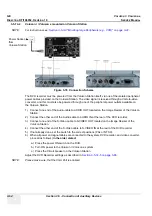
The DVD recorder must be powered from the Voluson Station itself, via one of the isolated peripheral
power cables provided on the Voluson Station. The video signal is received through a VGA-to-video
converter, and this must also be powered through one of the peripheral power outlets available on
the Voluson Station.
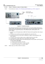
1.) Connect one end of the Audio-cable to AUDIO OUT located on the Image Resizer of the Voluson
Station.
2.) Connect the other end of the Audio-cable to AUDIO IN at the rear of the DVD recorder.
3.) Connect one end of the S-Video cable to S-VIDEO OUT located on the Image Resizer of the
Voluson Station.
4.) Connect the other end of the S-Video cable to S-VIDEO IN at the rear of the DVD recorder.
5.) If not already done, set the switch to the correct positions (PAL or NTSC).
6.) When all power and signal cables are connected to the system, DVD recorder, and video converter,
proceed as follows (
in the order stated
):
a.) Press the power ON switch on the DVD.
b.) Turn ON power to the Voluson i / Voluson e system.
c.) Press the Circuit breaker on the Voluson Station.
Adjust the DVD Recorder settings as described in
Section 3-5-14-5 on page 3-65
.
NOTE:
Please make sure, that the VGA Port is enabled.
Figure 3-78 Connection Scheme
Power Socket
from
Voluson Station
Summary of Contents for H48651KR
Page 2: ......
Page 11: ...GE VOLUSON i VOLUSON e DIRECTION KTI106052 REVISION 10 SERVICE MANUAL ix ZH CN KO ...
Page 44: ...GE VOLUSON i VOLUSON e DIRECTION KTI106052 REVISION 10 SERVICE MANUAL xlii Table of Contents ...
Page 514: ...GE VOLUSON i VOLUSON e DIRECTION KTI106052 REVISION 10 SERVICE MANUAL IV Index ...
Page 515: ......


