


Due to the pin number limitation, the CMP pass through mode is not supported by this
device, so the CMPx_MUXCR[PSTM] must be left as 0.
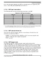
3.7.2.2 CMP input connections
The following table shows the fixed internal connections to the CMP.
Table 3-29. CMP input connections
CMP inputs
CMP0
IN0
CMP0_IN0
IN1
CMP0_IN1
IN2
CMP0_IN2
IN3
CMP0_IN3
IN4
—
IN5
—
IN6
IN7
6-bit DAC0 reference
1. This is the PMC bandgap 1V reference voltage. Prior to using as CMP input, ensure that you enable the bandgap buffer by
setting PMC_REGSC[BGBE]. See the device data sheet for the bandgap voltage (V
BG
) specification.
3.7.2.3 CMP external references
The 6-bit DAC sub-block supports selection of two references. For this device, the
references are connected as follows:
• VREFH–V
in1
input. When using VREFH, any ADC conversion using this same
reference at the same time is negatively impacted.
• VDD–V
in2
input
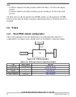
3.7.2.4 CMP trigger mode
The CMP and 6-bit DAC sub-block supports trigger mode operation when
CMP_CR1[TRIGM] is set. When trigger mode is enabled, the trigger event will initiate a
compare sequence that must first enable the CMP and DAC prior to performing a CMP
operation and capturing the output. In this device, control for this two-staged sequencing
is provided from the LPTMR. The LPTMR triggering output is always enabled when the
LPTMR is enabled. The first signal is supplied to enable the CMP and DAC and is
asserted at the same time as the TCF flag is set. The delay to the second signal that
triggers the CMP to capture the result of the compare operation is dependent on the
LPTMR configuration.
Chapter 3 Chip Configuration
KL02 Sub-Family Reference Manual, Rev. 2.1, July 2013
Freescale Semiconductor, Inc.
65


