


• The MCU is reset or enters Low-Power Stop modes.
• The MCU enters Normal Stop mode with ADACK not enabled.
When a conversion is aborted, the contents of the data registers, Rn, are not altered. The
data registers continue to be the values transferred after the completion of the last
successful conversion. If the conversion was aborted by a reset or Low-Power Stop
modes, RA and Rn return to their reset states.
25.4.4.4 Power control
The ADC module remains in its idle state until a conversion is initiated. If ADACK is
selected as the conversion clock source, but the asynchronous clock output is disabled,
that is CFG2[ADACKEN]=0, the ADACK clock generator also remains in its idle state
(disabled) until a conversion is initiated. If the asynchronous clock output is enabled, that
is, CFG2[ADACKEN]=1, it remains active regardless of the state of the ADC or the
MCU power mode.
Power consumption when the ADC is active can be reduced by setting CFG1[ADLPC].
This results in a lower maximum value for f
ADCK
.
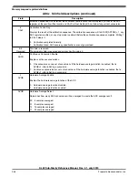
25.4.4.5 Sample time and total conversion time
For short sample, that is, when CFG1[ADLSMP]=0, there is a 2-cycle adder for first
conversion over the base sample time of four ADCK cycles. For high-speed conversions,
that is, when CFG2[ADHSC]=1, there is an additional 2-cycle adder on any conversion.
The table below summarizes sample times for the possible ADC configurations.
ADC configuration
Sample time (ADCK cycles)
CFG1[ADLSMP]
CFG2[ADLSTS]
CFG2[ADHSC]
First or Single
Subsequent
0
X
0
6
4
1
00
0
24
1
01
0
16
1
10
0
10
1
11
0
6
0
X
1
8
6
1
00
1
26
1
01
1
18
1
10
1
12
1
11
1
8
Functional description
KL02 Sub-Family Reference Manual, Rev. 2.1, July 2013
364
Freescale Semiconductor, Inc.


