


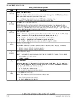


Table 21-11. MCG modes of operation (continued)
Mode
Description
Stop
Entered whenever the MCU enters a Stop state. The power modes are chip specific. For power
mode assignments, see the chapter that describes how modules are configured and MCG behavior
during Stop recovery. Entering Stop mode, the FLL is disabled, and all MCG clock signals are static
except in the following case:
MCGIRCLK is active in Normal Stop mode when all the following conditions become true:
• C1[IRCLKEN] = 1
• C1[IREFSTEN] = 1
1. If entering VLPR mode, MCG has to be configured and enter BLPE mode or BLPI mode with the Fast IRC clock selected
(C2[IRCS]=1). After it enters VLPR mode, writes to any of the MCG control registers that can cause an MCG clock mode
switch to a non low power clock mode must be avoided.
NOTE
For the chip-specific modes of operation, see the power
management chapter of this MCU.
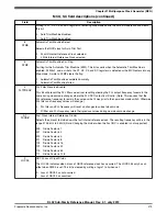
21.4.1.2 MCG mode switching
The C1[IREFS] bit can be changed at any time, but the actual switch to the newly
selected reference clocks is shown by the S[IREFST] bit. When switching between
engaged internal and engaged external modes, the FLL will begin locking again after the
switch is completed.
The C1[CLKS] bits can also be changed at any time, but the actual switch to the newly
selected clock is shown by the S[CLKST] bits. If the newly selected clock is not
available, the previous clock will remain selected.
The C4[DRST_DRS] write bits can be changed at any time except when C2[LP] bit is 1.
If the C4[DRST_DRS] write bits are changed while in FLL engaged internal (FEI) or
FLL engaged external (FEE), the MCGOUTCLK will switch to the new selected DCO
range within three clocks of the selected DCO clock. After switching to the new DCO,
the FLL remains unlocked for several reference cycles. DCO startup time is equal to the
FLL acquisition time. After the selected DCO startup time is over, the FLL is locked. The
completion of the switch is shown by the C4[DRST_DRS] read bits.
Chapter 21 Multipurpose Clock Generator (MCG)
KL02 Sub-Family Reference Manual, Rev. 2.1, July 2013
Freescale Semiconductor, Inc.
277


