25
Installing the Mobile Camera System
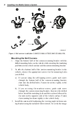
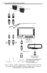
a) a camera-to-monitor extension cable that can be either
• one CAMCABLE-SHORT/-5/-10/-15/-20/-40
or
• two CAMCABLE-SHORT/-5/-10/-15/-20 connected in
series with adapter CAMCABLE-EXT
that is then connected to
• either the
CAM1
or
CAM2
input on the input/pow-
er/trigger wiring harness (CAMADP-INT-2) of the
CAMLCD-INT-56/CAMLCD-INT-70 monitor or
• one of the four camera inputs on the CAMBOX-
4NTSC/CAMBOX-4PAL control box (for use with the
CAMLCD-70 monitor) or
• one of the four camera inputs on the input/power/trigger
wiring harness (CAMADP-INT-4) of the CAMLCD-
INT-70-B
or
b) a special DVR system camera-extension cable that is con-
nected to one of the four camera inputs on the CAMDVR-4-B
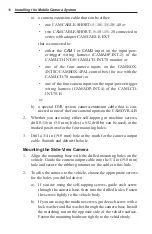
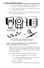
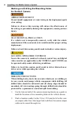
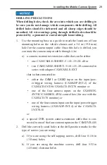
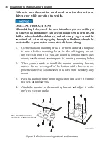
3. Drill the correctly sized holes at the drill-position marks for the
type of screws you are using:
a) If you are using the self-tapping screws, drill two 0.116 in
(3.0 mm) holes (a #32 drill bit can be used).
b) If you are using the machine screws, drill two 13/64 in
(5.2 mm) clearance holes.
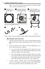
4. Drill a 3/4 in (19.0 mm) hole at the mark for the camera output
cable. Smooth and deburr the hole.

