16
Installing the Mobile Camera System
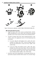
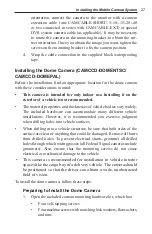
a) a camera extension cable that can be either:
• one CAMCABLE-SHORT/-5/-10/-15/-20/-40
or
• two CAMCABLE-SHORT/-5/-10/-15/-20 connected in
series with adapter CAMCABLE-EXT
that is connected to:
• either the
CAM1
or
CAM2
input on the input/pow-
er/trigger wiring harness (CAMADP-INT-2) of the
CAMLCD-INT-56/CAMLCD-INT-70 monitor or
• one of the four camera inputs on the CAMBOX-
4NTSC/CAMBOX-4PAL control box (for use with the
CAMLCD-70 monitor) or
• one of the four camera inputs on the input/power/trigger
wiring harness (CAMADP-INT-4) of the CAMLCD-
INT-70-B
or
b) a special DVR system camera-extension cable that is con-
nected to one of the four camera inputs on the CAMDVR-4-B
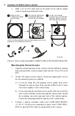
2. Whether you are using either self-tapping or machine screws,
drill 0.116 in (3.0 mm) holes (a #32 drill bit can be used) at the
marked positions for the four mounting holes.
3. Drill a 3/4 in (19.0 mm) hole at the mark for the camera output
cable. Smooth and deburr the hole.
Mounting the Side-View Camera
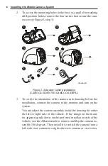
1. Align the mounting base with the drilled mounting holes on the
vehicle. Guide the camera output cable into the 3/4 in (19.0 mm)
hole and secure the rubber grommet on the cable in this hole.
2. To affix the camera to the vehicle, choose the appropriate screws
for the holes you drilled above:
a) If you are using the self-tapping screws, guide each screw
through the camera base, then into the drilled holes. Fasten
the screws tightly to the vehicle body.
b) If you are using the machine screws, guide each screw with a
lock washer and flat washer through the camera base. Install
the matching nut on the opposite side of the vehicle surface.
Fasten the mounting hardware tightly to the vehicle body.

