38
Connecting the Mobile Camera System
5. Connect a 12V–24 V trigger to the appropriate wire to signal when
the monitor should display Camera 1, 2, 3, or 4. The four-wire trigger
wiring harness is connected to
CAM TRIGGER
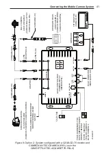
input (Figure 8 on
page 41):
• Green: Trigger for Camera 1
• White: Trigger for Camera 2
• Yellow: Trigger for Camera 3
• Blue: Trigger for Camera 4
The priority from highest to lowest for the camera triggers is: Camera
1 > Camera 2 > Camera 3 > Camera 4. In other words, the Camera 1
trigger has the highest priority and overrides other triggers. Connect
a 12–24V trigger to the appropriate wire to signal when the monitor
should display Camera 1, 2, 3, or 4.
6. The control box includes mirror/normal
(MIR/NOR)
switches for
each of the four camera inputs. Each switch can be set to the driver’s
preference.
7. RCA connections for audio and composite video are included for
connection to a VCR or DVR system.
8. Any connections made outside of the vehicle interior should be wrapped
in black waterproofing tape.
Option 3: System configured with CAMLCD-INT-70-B
monitor, as in the CAMSET70-NTSC4B/CAMSET70-PAL4B
/CAMSET70-N4BW
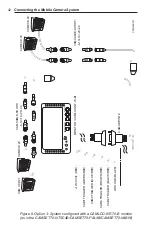
An example system is shown in Figure 9 on page 42.
1. Connect the 26-pin male connector on the monitor to the 26-pin
female connector on the CAMADP-INT-4 input/power/trigger wiring
harness.
2. One to four cameras can be connected to camera inputs 1 to 4 of the
input/power/trigger wiring harness, CAMADP-INT-4.
A CAMCABLE-SHORT/-5/-10/-15/-20/-40 connected to one of these
inputs can provide camera cable extension up to 131 ft (40 m).
Alternatively, using adapter CAMADP-EXT, two CAMCABLE-
SHORT/-5/-10/-15/-20 cables can be connected in series to achieve
lengths up to approximately 131 ft (40 m).

