36
Connecting the Mobile Camera System
4
Connecting the Mobile Camera System
This section describes how to connect four Mobile Camera System con-
figurations:
•
Option 1:
System configured with a CAMLCD-INT-56 monitor (as in
the CAMSET56-NTSC-2/CAMSET56-PAL-2) or CAMLCD-INT-70
monitor
•
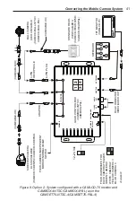
Option 2:
System configured with a CAMLCD-70 monitor and
CAMBOX-4NTSC/CAMBOX-4PAL (as in the CAMSET70-
NTSC-4/CAMSET70-PAL-4)
•
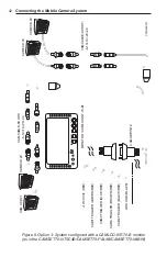
Option 3:
Option 3: System configured with a CAMLCD-INT-70-B
monitor (as in the CAMSET70-NTSC4B/CAMSET70-PAL4B)
•
Option 4:
Option 4: System configured with a CAMLCD-70 monitor
and CAMDVR-4-B digital video recorder
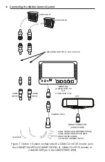
Option 1: Connections for system configured with
CAMLCD-INT-56/CAMLCD-INT-70/CAMLCD-MIR monitor,
as in the CAMSET56-NTSC-2/CAMSET56-PAL-2/
CAMSETMIR-4RW
For an illustration of a typical installation, see Figure 7 on page 40.
1. The included input/power/trigger wiring harness (CAMADP-INT-2)
has the following connections:
• Red
(RED/DC INPUT)
: Connect this to the 12V or 24V vehicle
battery. To avoid drawing current when the vehicle is not run-
ning, connect this wire to the vehicle ignition “accessory” or
“on” position.
• Black
(BLK/GND)
: Connect this to the vehicle or chassis ground.
• Green (
GREEN/REVERSE)
: Applies a 12V–24V signal to the
green wire functions as a trigger to display
CAM1
on the monitor.
If the camera connected to the
CAM1
input is used in a standard
rear-view application, you can connect the green wire to the re-
verse light circuit of the vehicle for automatic display of the rear-
view camera when the vehicle is in reverse. When this trigger is
removed, the monitor will return to standby mode with no image
displayed.


