33
•
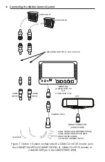
CAMLCD-INT-56/CAMLCD-INT-70: This monitor has an in-
put/power/trigger wiring harness that has two camera inputs,
power/ground, and two trigger wires.
•
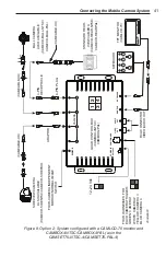
CAMLCD-70: This monitor has a single output cable that ei-
ther connects to a CAMBOX-4NTSC/CAMBOX-4PAL con-
trol box or to a CAMDVR-4-B digital video recorder. The
CAMBOX-4NTSC/CAMBOX-4PAL functions as the central
input/output “control box” for use with the CAMLCD-70 for
a split-screen capable, four-camera system. Alternatively, the
CAMDVR-4-B requires this monitor as the system display.
Many holes or an appropriately sized conduit will be needed to
accommodate all inputs and outputs for either of these systems.
•
CAMLCD-INT-70-B: This monitor has an input/power/trigger
wiring harness that has four camera inputs, power/ground, and
four trigger wires.
To install the monitor, follow these steps:
Mounting the Monitor in the Vehicle
AIRBAG DEPLOYMENT
Do not install equipment or route wiring in the deployment path
of an airbag.
Failure to observe this warning will reduce the effectiveness of
the airbag or potentially dislodge the equipment, causing serious
injury.
SEAT REMOVAL PRECAUTION
If a vehicle seat is temporarily removed, verify with the vehicle
manufacturer if the seat needs to be recalibrated for proper airbag
deployment.
Failure to heed this warning could result in death or serious injury.
LOCATING OPERATORS CONTROLS
Locate the camera(s), monitor, keyboard, control box, and digital
video recorder (as applicable) so the VEHICLE and SYSTEM can
be operated safely under all driving conditions.


