Operating manual
CNC 8055
CNC 8055i
GRAPHIC EDITOR
11.
·T· M
ODEL
S
OFT
: V02.2
X
·201·
Editin
g u
s
er scree
ns
(p
age
s)
an
d symbo
ls
11.2
Editing user screens (pages) and symbols
In order to edit a page or symbol, it is necessary to selected first by means of the EDIT option of
the UTILITIES mode of operation.
To edit or modify a page or symbol, use the options: GRAPHIC ELEMENTS, TEXTS, and
MODIFICATIONS.
The information contained in a page or symbol cannot occupy more than 4Kb of memory. Otherwise,
the CNC will issue the corresponding error message.
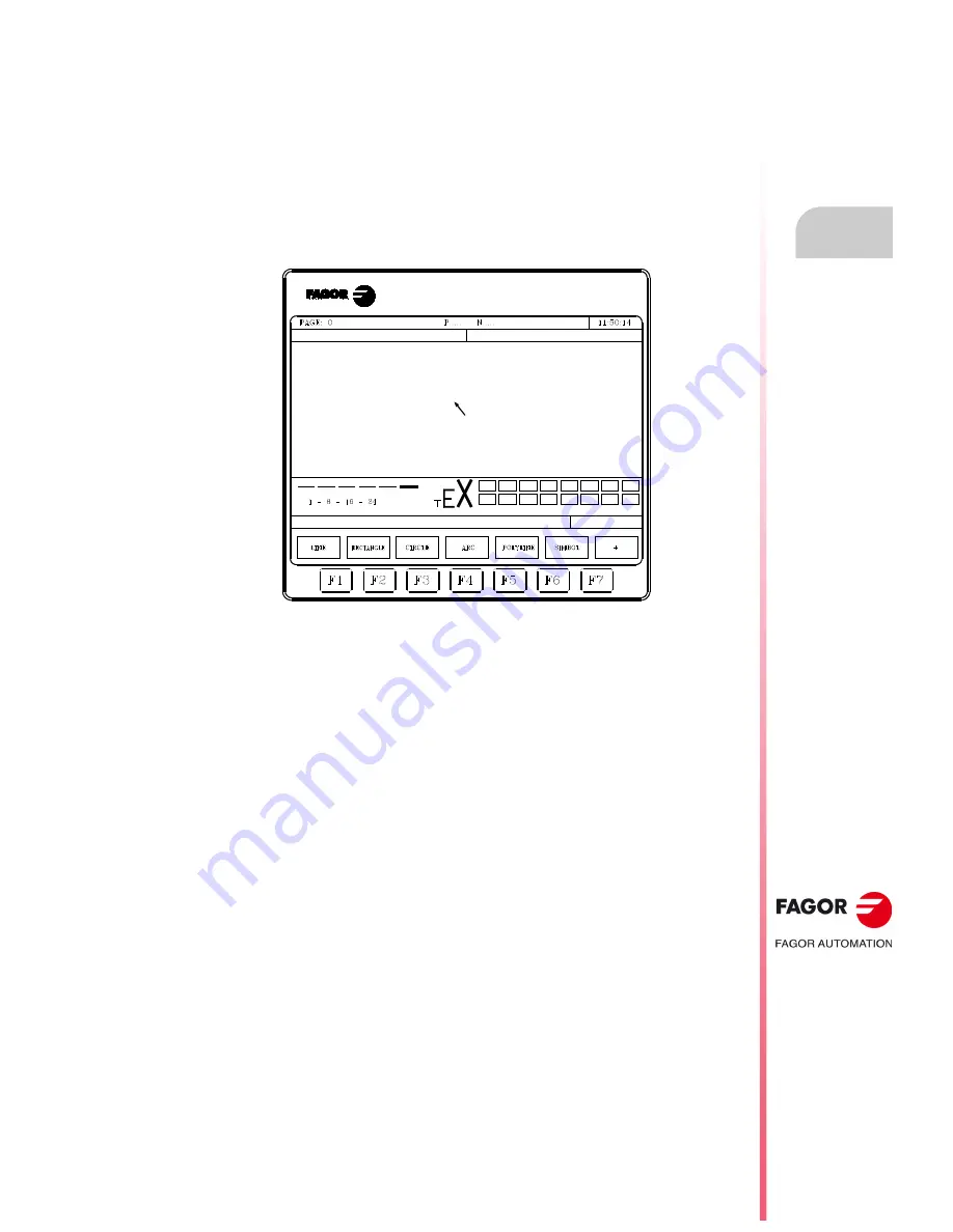
Once the page or symbol has been selected, the CNC will display a screen similar to this one:
The upper left-hand side of the screen will show the number of the page or symbol being edited.
The main window shows the selected page or symbol. When it is a new page or symbol, the main
window will display a blank page or empty symbol.
There is also a window at the bottom of the screen which shows the different editing parameters
and highlights their selected values. The various parameters available are:
• The type of drawing line used when defining the graphic elements.
• The cursor moving steps (cursor advance) in pixels.
• The letter size to create the texts for the pages and symbols.
• The background and foreground (main) colors for the graphic elements and for the letters.
One of the color rectangles shown has another rectangle in it. The inside rectangle indicates
the selected main color and the outside rectangle indicates the selected background color.
This window also shows the cursor position coordinates in pixels. The horizontal position is indicated
by the X value (1 through 638) and the vertical position by the Y value (0 through 334).
Once one of the options (GRAPHIC ELEMENTS, TEXTS or MODIFICATIONS) has been selected,
it will be possible to modify the editing parameters any time even while defining the graphic elements
and texts.
This way, it is possible to edit shapes of different lines and color as well as insert texts of different
sizes. Press [INS] to access this menu.
Once in this mode, the CNC will show the softkeys corresponding to the various options to modify
these parameters. These options are described next. Press [INS] again to quit this mode and return
to the previous menu.
Summary of Contents for CNC 8055
Page 1: ...CNC 8055 T Operating manual Ref 1705 Soft V02 2x...
Page 6: ...6 Operating manual CNC 8055 CNC 8055i T MODEL SOFT V02 2X...
Page 10: ...18 CNC 8055 CNC 8055i Declaration of conformity and Warranty conditions...
Page 14: ...10 CNC 8055 CNC 8055i Version history...
Page 20: ...16 CNC 8055 CNC 8055i Returning conditions...
Page 22: ...20 CNC 8055 CNC 8055i Additional notes...
Page 24: ...22 CNC 8055 CNC 8055i Fagor documentation...
Page 124: ...124 Operating manual CNC 8055 CNC 8055i 6 MANUAL T MODEL SOFT V02 2X Spindle movement...
Page 134: ...134 Operating manual CNC 8055 CNC 8055i 7 TABLES T MODEL SOFT V02 2X Tool Offset table...
Page 135: ...Operating manual CNC 8055 CNC 8055i TABLES 7 T MODEL SOFT V02 2X 135 Tool Offset table...
Page 138: ...138 Operating manual CNC 8055 CNC 8055i 7 TABLES T MODEL SOFT V02 2X Tool geometry table...
Page 196: ...196 Operating manual CNC 8055 CNC 8055i 10 PLC T MODEL SOFT V02 2X Logic analyzer...
Page 212: ...212 Operating manual CNC 8055 CNC 8055i 11 GRAPHIC EDITOR T MODEL SOFT V02 2X Modifications...
Page 240: ...240 Operating manual CNC 8055 CNC 8055i 13 DIAGNOSIS T MODEL SOFT V02 2X Interesting notes...
Page 253: ...Operating manual CNC 8055 CNC 8055i 14 T MODEL SOFT V02 2X 253...
Page 254: ...254 Operating manual CNC 8055 CNC 8055i 14 T MODEL SOFT V02 2X...
Page 255: ......


