background image

Multimeter Tests

108

MAX-610

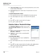
Resistive Balance

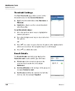
Threshold Settings

 button opens a new page that allows you to set the 

resistive balance thresholds.

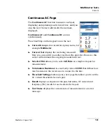
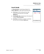
Test Status

 displays the current state of measurement or an error 

message.

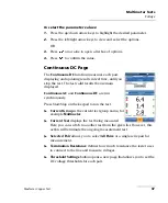
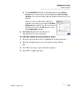
To select the parameter values:
1.

Press the up/down arrow keys to highlight the desired parameter.

2.

Press the left/right arrow keys to view and select the options.

OR

3.

Press 

 on a value to open a list box of options.

4.

Press 

 to confirm the value.

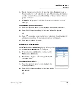
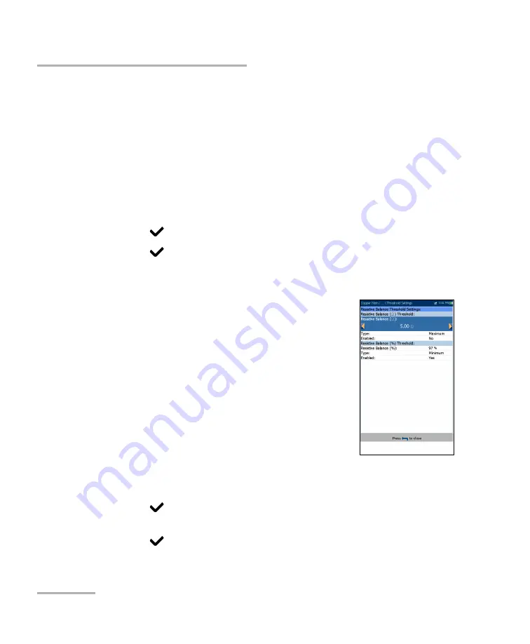
Resistive Balance Threshold Settings

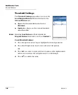
The 

Threshold Settings

 page allows you to set the 

Threshold Resistive Balance 

values for the test, in 

and %. 

Type

 is the threshold limit for each pair: either 

Maximum

 or 

Minimum

.

Enabled

 is a flag to use the current threshold: 

either 

Yes

 or 

No

.

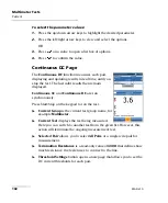
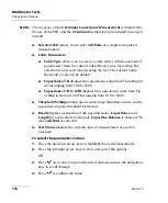
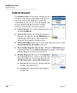
To set threshold values:
1.

Press the up/down arrow keys to highlight the 
desired parameter.

2.

Press the left/right arrow keys to view and select the options.

OR

3.

Press 

 on a value to open a list box of options or the alphanumeric 

editor screen and use the navigation keys to scroll through.

4.

Press 

 to confirm the value.

Summary of Contents for MaxTester Max-610

Page 1: ...User Guide Copper Test Set MaxTester MAX 610...

Page 2: ...FO for its use nor for any infringements of patents or other rights of third parties that may result from its use No license is granted by implication or otherwise under any patent rights of EXFO EXFO...

Page 3: ...ical Applications 2 Using the MAX 610 2 Cable Connections 5 Conventions 8 2 Safety Information 9 Electrical Safety Information 10 Equipment Ratings 11 3 Getting Started with the MaxTester 13 Turning t...

Page 4: ...esult 83 Results Summary 83 Read Result Menu 84 Upload 89 Export 90 7 Multimeter Tests 93 Multimeter Main Page 93 Voltage 94 Current 99 Resistance 104 Resistive Balance 107 Isolation 110 Capacitance O...

Page 5: ...212 12 RFL 213 Single Pair 213 Separate Good Pair 215 RFL Cable Setup 218 Result Details 220 13 Copper Auto Tests 223 Main Menu 223 POTS Auto Test 224 User Auto Test 228 Result Details 240 Profile De...

Page 6: ...nts vi MAX 610 16 Warranty 259 General Information 259 Liability 260 Exclusions 261 Certification 261 Service and Repairs 262 EXFO Service Centers Worldwide 263 263 A Technical Specifications 265 Inde...

Page 7: ...Engineering Inc makes reasonable efforts to ensure compliance to the applicable standards The limits set by these standards are designed to provide reasonable protection against harmful interference w...

Page 8: ...44 2380 246810 Equipment Type Environment Test Measurement Industrial Trade Name Model No Copper Test Set MaxTester 610 Standard s to which Conformity is declared EN 61010 1 2001 Edition 2 0 Safety r...

Page 9: ...which makes it ideal for field use Its display is a back lit LCD featuring 480 x 800 resolution A membrane keypad mounted on the face of the unit features a 14 button keypad used to operate the test...

Page 10: ...ective and FaultMapper Using the MAX 610 The MAX 610 is tested for IP54 compliance which means that it is not affected by dust or water splashing against the enclosure from any direction This protecti...

Page 11: ...Introducing the MaxTester MAX 610 MaxTester Copper Test 3 Using the MAX 610 Right Front DC Power Door USB Client Port Power LED Battery LED Speaker...

Page 12: ...Introducing the MaxTester MAX 610 4 MAX 610 Using the MAX 610 Back Note The MAX 610 enclosure may become warm during normal use Battery Door Screws Screws...

Page 13: ...the MAX 610 device Note When connecting a DSL cable to the WAN port use the RJ 45 plug end of the cable provided with the unit There is a 1500 V maximum transient voltage on telecom ports Basic insul...

Page 14: ...g the MaxTester MAX 610 6 MAX 610 Cable Connections Secondary Tip A wire of phone line Secondary Ring B wire of phone line Shield of phone line Primary Tip A wire of phone line Primary Ring B wire of...

Page 15: ...ical testing of common telephone line conductors within the ranges specified in the Technical Specifications on page 265 The device is not intended to be used on telephone lines having voltages greate...

Page 16: ...eed unless you understand and meet the required conditions CAUTION Indicates a potentially hazardous situation which if not avoided may result in minor or moderate injury Do not proceed unless you und...

Page 17: ...MPORTANT When you see the following symbol on your unit make sure that you refer to the instructions provided in your user documentation Ensure that you understand and meet the required conditions bef...

Page 18: ...g detachable mains supply cords with inadequately rated cords may result in overheating of the cord and create a fire risk The adapter shall have the appropriate safety mark e g UL CSA TUV CE etc that...

Page 19: ...easing linearly to 50 at 40 C 104 F 95 non condensing 0 to 80 non condensing Maximum operation altitude 3000 m 9843 ft Pollution degree 2 when plugged to AC mains b 3 when operated from batteries c b...

Page 20: ......

Page 21: ...before turning the unit off or else any changes are lost See Save Profile page 29 for more information Regional LCD and energy saving settings Test results saved internally vs USB There are two ways...

Page 22: ...Using Menus and Keypad You can access various tools from the keypad or menu Menu options may differ depending on your unit configuration Home menu is where you can access Copper tests and System Sett...

Page 23: ...tivate the corresponding on screen function button Home button brings you to the Copper Main page of the MaxTester MAX 610 or to the Home page Using Online Help Online help is available at any time Mo...

Page 24: ......

Page 25: ...te between Copper Test and System Settings using the left right arrow keys on the keypad Press to bring up the sub menu of the selected icon Copper Test opens the Copper Main menu displaying the coppe...

Page 26: ...atus Power Schemes and Calibration Software Options allow you to enable disable purchased feature options Information displays information About EXFO and unit details pertaining to hardware software p...

Page 27: ...t System Settings and then Display and Language 2 Use the up down arrow keys to select the setting to change 3 Press to select it By using the up down arrow keys you can switch between preset brightne...

Page 28: ...ht saving period To set the date and time 1 From select System Settings and then Date and Time 2 Use the arrows to select any of the date or time settings 3 Press to enable the modification controls F...

Page 29: ...endently for the battery or DC power modes This is useful for example if you want to save battery power but do not want to be hindered by unwanted switches between modes when using DC power Power off...

Page 30: ...s 1 From select System Settings and then Power 2 Select the Power Schemes tab 3 Under DC IN or BATTERY use the arrow keys to select Idle suspend timeout modes Press to view the list of available choic...

Page 31: ...completed Calibration In Progress is displayed when the procedure has been started and not yet completed Calibration Aborted is displayed when the procedure has been started but the DC plug was remove...

Page 32: ...Options which are present on the unit Possible options are as follow TDR RFL FaultMapper Pair Detective 30 MHz Wideband Testing Near End Crosstalk Stressed Balance Test Far End Device Test Control Pla...

Page 33: ...formation About EXFO The About tab contains contact information should you require technical assistance MAX 610 Information The Information tab displays information about the product software and memo...

Page 34: ...load Save Result page Copper User Auto Test Read Upload Result Summary page All tests Copper Read Upload Result A Wi Fi symbol in the top right hand corner of the navigation bar identifies whether or...

Page 35: ...g a green or yellow icon similar to the Wi Fi symbol described above Disable Upload option disables uploading your files via Wi Fi or Ethernet You can export results to a USB memory device To select t...

Page 36: ...c value for the signalling port used to establish an IP network session Username Password is your login ID and password Mode is either Active or Passive for the file transfer mode Transfer Type is set...

Page 37: ...cure Wi Fi networks in range and presently connected Unsecured Wi Fi networks are not supported The last three networks that were connected are also listed whether or not they are presently connected...

Page 38: ...connect your MaxTester to a Wi Fi network 1 Press the down arrow key to highlight the list box and press to get into the list 2 In the list press the up down arrows to select the desired network 3 Pre...

Page 39: ...gle In this case please use WPA2 encryption Password opens the alphanumeric editor screen allowing you to enter the desired Wi Fi network s password Join function key replaces Done on the editor scree...

Page 40: ...h 4094 The entry is available only when VLAN Support is Enable Vendor ID is the name of the unit This entry is available only when Access Mode is DHCP Local Mac Address is the internal MAC address of...

Page 41: ...1 is the address of the primary domain name server to be used by the unit If DNS is unavailable enter 0 0 0 0 DNS2 is the address of the secondary domain name server to be used by the unit If DNS is u...

Page 42: ......

Page 43: ...chnology In addition it utilizes noise measurements longitudinal balance tests and power spectral density tests to assist in the installation maintenance and troubleshooting of copper cables Copper Te...

Page 44: ...ion profile A Profile Default is provided with a predefined set of parameters for all test applications Note Cable parameters are not included in these profiles but can be configured in Setup Select P...

Page 45: ...ed by pressing No You can terminate the process by pressing Cancel Copy from USB allows you to copy all profiles found on an external USB device to the unit Delete Profile allows you to delete a profi...

Page 46: ...e between the configuration icons 1 Press the up down left right arrow keys on the keypad to select an icon 2 Press to confirm your selection Select Profile The Select Profile page lists the available...

Page 47: ...this profile in the Threshold Settings or parameters of a particular test Each test displays a sub menu of test icons to select and setup To select a test 1 Press the up down left right arrow keys on...

Page 48: ...your selection Noise Tests Profile Details The profile details Noise Tests main menu allows you to view the test threshold and parameters of the following tests VF Noise Power Influence VF Impulse No...

Page 49: ...Tone To navigate between the test profiles 1 Press the up down left right arrow keys on the keypad to select an icon 2 Press to confirm your selection Auto Test Profile Details The profile details Aut...

Page 50: ...profile which cannot be removed Selected Profile displays the profile name in use To delete a profile 1 Press the up down arrow keys to highlight the entry to be removed and press 2 Press the Delete f...

Page 51: ...de the following pages General Standard Identification File Name and Buzzer Current settings are kept in memory and are independent of the profiles Factory Default allows you to revert the Phone Book...

Page 52: ...rming the copper tests It can include a maximum of 50 groups of up to 3 individual entries each The functions are as follow Select Group Entry Phone Book Details Add Group Clone Group Delete Group Loa...

Page 53: ...OR 2 Press to cancel your selection and go back to the Phone Book menu Phone Book Details The Phone Book Details page allows you to view and modify the Phone Book parameters of the currently highligh...

Page 54: ...e parameters of the Phone Book To view and modify the group details 1 Press the up down arrow keys to highlight the desired parameter 2 Press the left right arrow keys to view and select the options O...

Page 55: ...att tone Drop battery Quiet line for additional line types Enable displays either Yes or No Add function key adds the new group entry to the Phone Book To add a new group entry 1 Press the up down arr...

Page 56: ...ll entries by Group ID The list can display a maximum of 50 entries Group In Use displays the Group ID number in use To clone a group entry 1 Press the up down arrow keys to highlight the desired entr...

Page 57: ...e group number in use To delete a group entry 1 Press the up down arrow keys to select the entry to be removed 2 Press the Delete function key to remove the selected entry from the Phone Book If you t...

Page 58: ...button imports the selected phone book You will be prompted for confirmation since this action will overwrite the current phone book Cancel button removes the confirmation warning message without imp...

Page 59: ...e book to save By default the name is phone_book csv The Storage Location lists the save destinations MT internal memory USB Save button saves the selected file Note The unit will overwrite any docume...

Page 60: ...pplication To access the Dialer function 1 On the Home pane use the up down arrow keys to highlight Copper Test then press 2 From the Copper Main page select Dialer and press Dialer The Dialer functio...

Page 61: ...select a number from the Phone Book Function Keys Dial Hang Up allows you to dial the selected or entered number or hang up the dialer Add To PhoneBook saves the entered number to the Phone Book Mute...

Page 62: ...s Pause to enter a 1 second pause while dialing For example pressing Pause consecutively 3 times creates a 3 second pause 3 Move left or right in the text box by using Cursor Left Right function keys...

Page 63: ...utomatically entered in the Enter Number field of the Dialer page Select from Phone Book The Select Entry read only page lists entries by Group ID and Entry Name Type There is 1 group of 3 factory def...

Page 64: ...one Drop battery Quiet line for additional line types Enable displays either Yes or No Add function key adds the new group entry to the Phone Book To add a number to the phone book 1 Press the up down...

Page 65: ...pad to select an icon 2 Press to confirm your selection Select Cable The Select Cable page lists entries by Cable ID and Cable Name There are a minimum of 10 factory default cable entries which cannot...

Page 66: ...nce T R A B specifies a value for the capacitance per length constant Capacitance T R to GND A B to E specifies a value for the capacitance per length to ground constant Resistance specifies a value f...

Page 67: ...y into the Cable Book using the following parameters for the currently highlighted Cable ID Cable ID displays the cable ID number This parameter that cannot be modified Cable Name is the name of the c...

Page 68: ...d function key adds the new cable entry to the Cable Book To add a new cable entry 1 Press the up down arrow keys to highlight the desired parameter 2 Press the left right arrow keys to view and selec...

Page 69: ...Cable ID and Cable Name The list can display a maximum of 25 entries of which 10 are factory default Cable In Use displays the Cable ID number in use To clone a cable entry 1 Press the up down arrow k...

Page 70: ...le In Use displays the Cable ID number in use To delete a cable entry 1 Press the up down arrow keys to highlight the entry to be removed and press 2 Press the Delete function key to remove the entry...

Page 71: ...ings Each parameter is described below Cable Temperature specifies the temperature of the cable under test in either F Fahrenheit or C Celsius units Capacitance Measurement is either 3 Terminal or 2 T...

Page 72: ...e internal memory of the MaxTester Landscape Mode Settings Default Graph Mode sets the default graph viewing mode to either Portrait or Landscape Screen Rotation sets your preferred default rotation o...

Page 73: ...ers Preset for the page Measurement Units Distance lists the measurement units for distance in feet or meters Temperature lists the measurement units for temperature in F Fahrenheit or C Celsius Level...

Page 74: ...s Enabled on the FED Setup page the termination resistance of the FED is the same as the MaxTester except when Standard is set to ITU the termination resistance of the FED will remain at 120 since it...

Page 75: ...single and auto test result file when saving them The parameters are as follow User Name User ID allow you to enter up to 25 alphanumeric characters in each field Test From To list the following valu...

Page 76: ...CPE CROSSBOX and FRAME When any of these are selected the Delete and Accept buttons are disabled A maximum of 20 different entries can be added To manage the list 1 Press the left right arrow keys to...

Page 77: ...bled entries are not shown Date and Time value format depends on the format selected in System Settings This entry cannot be disabled Separator allows you to choose a value to separate the enabled ent...

Page 78: ...Press to get into the list 2 Use the up down arrow keys to select the desired entry 3 Press to come out of the list 4 Press the up or down arrow key to activate the Up Down buttons 5 Using the left r...

Page 79: ...sh timeout from 1 to 15 minutes Hush Buzzer button mutes the sounding buzzer Note Upon raising the hazardous voltage flag the MaxTester opens the relays and you will have to press Start Stop on the ke...

Page 80: ...t Lead Compensation routine allows you to perform resistance and capacitance compensation The page displays the Pass Fail status of the last compensation done Note Always perform a test lead compensat...

Page 81: ...Open T R G A B E Shorted By connecting the T R G A B E of a customer s pair CPE to the customer side of the FED control signals are sent to the FED by the MaxTester in order to open short or pass thr...

Page 82: ...to the customer side of the FED are open circuited 3 For T R G A B E Shorted set the FED so that T R G A B E are all short circuited connected to each other at the customer side of the FED Note P U T...

Page 83: ...When FED is Enabled and you start a test the MaxTester will warn you if the FED battery level is low Select OK to close the message and run the test FED States are displayed in the Current Test line a...

Page 84: ...the factory defaults for the following Single Test defaults sets the default FED state values for all the individual tests except Auto Test User Auto Test defaults sets the default FED state values f...

Page 85: ...Copper Tests MaxTester Copper Test 77 FED Setup Multimeter The Multimeter tab lists the default FED States set for all multimeter tests Noise The Noise tab lists the default FED States set for all no...

Page 86: ...MAX 610 FED Setup Frequency The Frequency tab lists the default FED States set for all frequency tests Other The Other tab displays the default FED States set for all other tests such as TDR and RFL...

Page 87: ...ops up Selecting Save displays the Save Result screen where the following information can be entered Identification Fields User Name User ID display the values set up in the Application Settings Ident...

Page 88: ...Settings File Name Save button confirms if the Result File Name is saved successfully Export Report Report Format is HTML MHTML or XML You can generate and export HTML MHTML or XML reports from any sa...

Page 89: ...y to highlight the desired value OR 4 Press the left arrow key to erase the existing value and then use the alphanumeric keypad to enter a value To cancel the entry press 5 Press to accept the value S...

Page 90: ......

Page 91: ...y saved The page lists all saved result files by test date and time The format of Test Date Time is per the selection in System Settings Result files can be loaded from either the MT internal memory o...

Page 92: ...h lead combination and cable parameters of the test Profile Details displays the thresholds and setup parameters of the test Phone Book displays the phone entry dialed during the test FED Details disp...

Page 93: ...result Result File Name Test Date and Time Test Group Test Identification Test Modes Test Lead Compensation displays read only Date and Time and Pass Fail Status of the compensated resistance and capa...

Page 94: ...generate a report in either HTML MHTML or XML format Upload in User Auto Test only allows you to transfer an Auto Test result file to an FTP site or USB device via the presently selected method Wi Fi...

Page 95: ...ters of the selected test Profile Details The Profile Details page displays read only test thresholds and or parameters information about the setup of the selected test Profile Name is the file name o...

Page 96: ...ls when loading a results file It contains information about group entries such as group ID name phone numbers and tags If the dialer was not used during the test the Phone Book icon will not appear a...

Page 97: ...r All Uploaded status column displays a successful failed or no upload for each file Upload button transfers the selected files to the designated location Delete button removes selected XML files from...

Page 98: ...t Format is HTML MHTML or XML Export button transfers the selected file s to the internal memory or USB device in the selected report format To export previously saved test results 1 Press the left ri...

Page 99: ...er Test Results MaxTester Copper Test 91 Export 8 Press the left right arrow keys to select the desired format OR 9 Press to display the list and select the value 10 Press the down arrow key to press...

Page 100: ......

Page 101: ...h capacitance To access Multimeter tests From the Copper Main pane highlight Multimeter and press to open the Multimeter menu Multimeter Main Page The Multimeter menu allows you to select and run the...

Page 102: ...ys the test being measured Here you can switch to another test from the given list However this action will terminate the ongoing measurement test Selected Pair allows you to select All Pairs or a sin...

Page 103: ...e Threshold Settings page allows you to set the Threshold Voltage for each pair Type is the threshold limit for each pair either Maximum or Minimum Enabled is a flag to use the voltage threshold eithe...

Page 104: ...eing measured Here you can switch to another test from the given list However this action will terminate the ongoing measurement test Selected Pair allows you to select All Pairs or a single wire pair...

Page 105: ...n remain displayed Continuous AC and Continuous DC are run synchronously Press Start Stop on the keypad to run the test Current Group is the current test group name for example Multimeter Current Test...

Page 106: ...air Test Status displays the current state of measurement or an error message To select the parameter values 1 Press the up down arrow keys to highlight the desired parameter 2 Press the left right ar...

Page 107: ...est from the given list However this action will terminate the ongoing measurement test Selected Pair allows you to select All Pairs or a single wire pair for measurement Termination Resistance is a r...

Page 108: ...shold Settings page allows you to set the Threshold Current for each pair Type is the threshold limit for each pair either Maximum or Minimum Enabled is a flag to use the current threshold either Yes...

Page 109: ...ng measured Here you can switch to another test from the given list However this action will terminate the ongoing measurement test Selected Pair allows you to select All Pairs or a single wire pair f...

Page 110: ...layed Continuous AC and Continuous DC are run synchronously Press Start Stop on the keypad to run the test Current Group is the current test group name for example Multimeter Current Test displays the...

Page 111: ...elected wire pair Test Status displays the current state of measurement or an error message To select the parameter values 1 Press the up down arrow keys to highlight the desired parameter 2 Press the...

Page 112: ...rom the given list However this action will terminate the ongoing measurement test Selected Pair allows you to select All Pairs or a single wire pair for measurement Cable Parameters Cable Type allows...

Page 113: ...istance Threshold Settings page allows you to set the Resistance for each pair Type is the threshold limit for each pair either Maximum or Minimum Enabled is a flag to use the current threshold either...

Page 114: ...easurement test Selected Pair allows you to select All Pairs or a single wire pair for measurement Cable Parameters Cable Type allows you to select a cable entry with its associated parameters from th...

Page 115: ...compares the resistance of each leg This test requires you to short Tip and Ring T R to ground at the far end T R G short before proceeding with the test Snapshot The resistive balance Snapshot shows...

Page 116: ...options 4 Press to confirm the value Resistive Balance Threshold Settings The Threshold Settings page allows you to set the Threshold Resistive Balance values for the test in and Type is the threshold...

Page 117: ...the pass fail status for Resistive Balance in and Profile Details The Profile Details page displays read only Resistive Balance thresholds Profile Name is the file name of the selected saved results T...

Page 118: ...displays the test being measured Here you can switch to another test from the given list However this action will terminate the ongoing measurement test Selected Pair allows you to select All Pairs o...

Page 119: ...ameter 2 Press the left right arrow keys to view and select the options OR 3 Press on a value to open a list box of options or the alphanumeric editor screen and use the navigation keys to scroll thro...

Page 120: ...measurement test Selected Pair allows you to select a single wire pair for measurement Soak Voltage allows you to apply a voltage value to the pair s currently under test If your unit has the HIVOLT...

Page 121: ...ond for the wire pair s under test Test Status displays the current state of measurement or an error message To select the parameter values 1 Press the up down arrow keys to highlight the desired para...

Page 122: ...played beside the Current Test Here you can switch to another test from the given list However this action will terminate the ongoing measurement test Note The accuracy of the 2 Terminal Capacitance M...

Page 123: ...es 1 Press the up down arrow keys to highlight the desired parameter 2 Press the left right arrow keys to view and select the options OR 3 Press on a value to open a list box of options and use the na...

Page 124: ...in nF mi ranging from 10 0 to 500 0 Capacitance T R to GND displays the capacitance value from Tip or Ring to Ground in nF mi ranging from 10 0 to 500 0 Threshold Settings button opens a new page that...

Page 125: ...reshold limit for each pair either Maximum or Minimum Enabled is a flag to use the current threshold either Yes or No To set threshold values 1 Press the up down arrow keys to highlight the desired pa...

Page 126: ...imeter test from the given list However this action will terminate the ongoing measurement test Threshold Settings button opens a new page that allows you to set the Ground Resistance Threshold for th...

Page 127: ...diagram at any time by pressing the Hookup Diagram button In this case the test does not start when you press the Ok button to close the Confirmation window Test Status displays the current state of m...

Page 128: ...eft right arrow keys to view and select the options OR 3 Press on a value to open a list box of options or the alphanumeric editor screen and use the navigation keys to scroll through 4 Press to confi...

Page 129: ...ill terminate the ongoing measurement test Noise Filter is a fixed value set to C message Termination Resistance is a read only value of 600 Threshold Settings button opens a new page that allows you...

Page 130: ...se the current threshold either Yes or No Note Disabling Good Balance will also disable the Marginal Balance threshold even if you Enabled it To set threshold values 1 Press the up down arrow keys to...

Page 131: ...ays the Stressed Balance results and the pass fail status Test Group is the overall test group of the selected saved results file for example Multimeter Test Identification is the test type of the gro...

Page 132: ......

Page 133: ...of a series of 10 consecutive individual tests and applies a high voltage to the line during isolation testing Before proceeding with this test ensure the line is inactive At the start of any test the...

Page 134: ...option configured the Soak Voltage parameter values are extended up to 500 V maximum Default is inherited from Multimeter Isolation test Cable Setup button opens a new page that allows you to set the...

Page 135: ...cable is filled with Aircore Jelly Pulp 5 PR or 2 PR Setup in the Cable Book Velocity of Propagation read only entry is the velocity of propagation for the cable as a ratio of the speed of light Setup...

Page 136: ...Good VF AC Balance sets the good VF AC balance threshold Marginal VF AC Balance sets the marginal VF AC balance threshold Isolation sets the isolation resistance threshold Type is a read only field di...

Page 137: ...function allows you to run and edit the TDR test The test runs continuously for the selected parameters after the first cycle of the Pair Detective test After saving the results the Pair Detective re...

Page 138: ...ues will be updated by TDR test Pulse Width is a non editable value that is updated dependent on whether the parameters are set to Auto or manual Cable Setup button opens a new page that allows you to...

Page 139: ...se function keys and displays the Continuous page Result displays the distance to the most significant reflection Test Status displays the current state of measurement or an error message To select th...

Page 140: ...Aircore Jelly Pulp 5 PR or 2 PR Setup in the Cable Book Velocity of Propagation read only entry is the velocity of propagation for the cable as a ratio of the speed of light Setup in the Cable Book C...

Page 141: ...the cable is filled with Aircore Jelly Pulp 5 PR or 2 PR Velocity of Propagation is the velocity of propagation for the cable as a ratio of the speed of light Cable Temperature is the temperature of...

Page 142: ...s 134 MAX 610 Pair Detective Result Details Multimeter The read only Multimeter page displays detailed results saved from running the Pair Detective test Please refer to Multimeter on page 129 for mor...

Page 143: ...the Cable Parameters for the Current Test Result displays the cable faults in text and graphical format Note Some displayed resistive faults may be effective faults For example if a strap is present...

Page 144: ...h and Cable Temperature for the FaultMapper test All other Cable Parameters are read only and correspond to the current cable book entry as selected in Setup Cable Book Cable Details page Cable Type a...

Page 145: ...hange the temperature of the cable under test in either degree C or F To select the parameter values 1 Press the up down arrow keys to highlight the desired parameter 2 Press the left right arrow keys...

Page 146: ...to select the button and press to open the page Result displays the cable fault details Note Some displayed resistive faults may be effective faults For example if a strap is present a T G short may...

Page 147: ...acitance T R A B is the value for the capacitance per length constant Capacitance T R to GND A B to E is the value for the capacitance per length to ground constant Attenuation 300 kHz is the value fo...

Page 148: ...er FaultMapper Profile Details The Profile Details page displays read only FaultMapper Test Parameters Profile Name is the file name of the selected saved results Test Identification is the test type...

Page 149: ...ht Noise Tests and press to open the menu Noise Tests Main Page The Noise Tests menu allows you to select and run the displayed tests VF Noise Power Influence VF Impulse Noise WB PSD Noise WB Impulse...

Page 150: ...t However this action will terminate the ongoing measurement test VF Noise Filter allows you to define the voice frequency noise filter to be used dependent on ITU or ANSI Standard mode and Noise Filt...

Page 151: ...e Threshold Settings page allows you to set the Threshold VF Noise values for the test Type is the threshold limit either Maximum or Minimum Enabled is a flag to use the current threshold either Yes o...

Page 152: ...Noise Tests 144 MAX 610 VF Noise Result Details The Results Details read only page displays the VF Noise value and the pass fail status...

Page 153: ...nate the ongoing measurement test VF Noise Filter allows you to define the voice frequency noise filter to be used dependent on ITU or ANSI Standard mode and Noise Filter set in Setup Application Sett...

Page 154: ...s the x axis and y axis limits to full scale Return To Test removes these function keys and displays the Detection page Result displays a value and graph of the Power Influence measurement and pass fa...

Page 155: ...urrent threshold either Yes or No To set threshold values 1 Press the up down arrow keys to highlight the desired parameter 2 Press the left right arrow keys to view and select the options OR 3 Press...

Page 156: ...tion will terminate the ongoing measurement test VF Noise Filter allows you to define the voice frequency noise filter to be used dependent on ITU or ANSI Standard mode and Noise Filter set in Setup A...

Page 157: ...Noise To select the parameter values 1 Press the up down arrow keys to highlight the desired parameter 2 Press the left right arrow keys to view and select the options OR 3 Press on a value to open a...

Page 158: ...y a value between 1 and 6 dB Mid Counter allows you to set the threshold value for this counter Type is the threshold limit of the Mid Counter either Maximum or Minimum Enabled is a flag to use the cu...

Page 159: ...MaxTester Copper Test 151 VF Impulse Noise Result Details The Results Details read only page displays the High Mid Low VF Impulse Noise Count and Detection Level values and the pass fail status of th...

Page 160: ...ion will terminate the ongoing measurement test Bandwidth sets the frequency range for the test Noise Filter defines the filter currently enabled Options are None ISDN E HDSL F ADSL G ADSL ADSL2 VDSL...

Page 161: ...ght arrow keys to pan the x axis and the up down arrow keys to pan the y axis 1 1 resets the x axis and y axis limits to full scale Return To Test removes these function keys and displays the previous...

Page 162: ...Settings configured in Application Settings General This mode generates the following function keys Portrait Mode is used to change the screen orientation from landscape to portrait Select Graph open...

Page 163: ...Threshold Settings The Threshold Settings page allows you to set the RMS Noise Threshold parameters for the test Type is the threshold limit for each pair either Maximum or Minimum Enabled is a flag...

Page 164: ...oom references the middle of the x y axis and not the cursor position Press the arrow keys as follows Right x axis zoom in Left x axis zoom out Up y axis zoom in Down y axis zoom out Pan use left righ...

Page 165: ...e ongoing measurement test WB Noise Filter displays the filter currently enabled Options are None ISDN E HDSL F ADSL G ADSL ADSL2 VDSL VDSL2 8 VDSL2 12 VDSL2 17 VDSL2 30 Termination Resistance lists t...

Page 166: ...test Test Status displays the current state of measurement or an error message To select the parameter values 1 Press the up down arrow keys to highlight the desired parameter 2 Press the left right a...

Page 167: ...old value for this counter Type is the threshold limit for each pair either Maximum or Minimum Enabled is a flag to use the current threshold either Yes or No To set threshold values 1 Press the up do...

Page 168: ...Results Details read only page displays the WB Impulse Noise Count Detection Level and pass fail status Profile Details The WB Impulse Noise Profile Details read only page displays the test thresholds...

Page 169: ...last valid results then remain displayed Current Group is the current test group name for example Noise Tests Current Test displays the test being measured Here you can switch to another Noise test fr...

Page 170: ...T1 R1 A1 B1 pairs will be terminated at the FED The hookup diagram uses graphic and textual components Proceed button closes the hookup diagram prompt and starts the test Cancel button closes the hoo...

Page 171: ...at allows you to set the NEXT Spot Threshold for the test Step Freq button automatically enters transfers the Frequency Step value into the Frequency value If the step size is less than 10 kHz but not...

Page 172: ...alue Spot Threshold Settings The Threshold Settings page allows you to set the threshold values for the NEXT Spot test Type is the threshold limit either Maximum or Minimum Enabled is a flag to use th...

Page 173: ...Noise Tests MaxTester Copper Test 165 NEXT Spot Result Details The Spot Results Details read only page displays the saved pass fail status NEXT and Frequency TX values...

Page 174: ...the bandwidth of the frequency range for the test Available frequency bandwidths are 2 2 MHz 8 MHz 12 MHz 17 6 MHz and 30 MHz Termination Resistance lists a choice of resistance values for the termin...

Page 175: ...firmation window is prompted before every NEXT test is started if you selected Yes for the Show hookup diagram You can select No to hide the diagram next time you run the test However you can check th...

Page 176: ...le of the current x axis limits Zoom references the middle of the x y axis and not the cursor position Press the arrow keys as follows Right x axis zoom in Left x axis zoom out Up y axis zoom in Down...

Page 177: ...ettings page allows you to set the Crosstalk threshold values at fixed and periodic frequencies Type is the threshold limit either Maximum or Minimum Enabled is a flag to use the current threshold eit...

Page 178: ...raph as follows Cursor press the left right arrow keys to decrease increase the values by moving the cursor Press and hold the left right arrow keys to accelerate the cursor Press to recall the cursor...

Page 179: ...ys detailed read only test thresholds and parameters for both Spot and Spectrum modes Profile Name is the file name of the selected saved results Test Group is the overall test group of the selected s...

Page 180: ......

Page 181: ...pper Main pane highlight Frequency Tests and press to open the menu Frequency Tests Main Page The Frequency Tests menu allows you to select and run the displayed tests VF AC Balance WB Balance WB Atte...

Page 182: ...igher the dB reading The name of the frequency test depends on the selected Standard ANSI VF Balance ITU AC Balance Active The Active function takes a balance measurement displaying and updating resul...

Page 183: ...ue VF AC Balance Active Threshold Settings The Threshold Settings page allows you to set the Active VF AC Balance Threshold values for the test VF AC Balance sets the active balance threshold Type is...

Page 184: ...t results of the active and passive VF Longitudinal Balance tests will generally be different due to the fact they use different measurement techniques Current Group is the current test group name for...

Page 185: ...ement or an error message Note The selected Standard in Setup Application Settings determines the name of the frequency test ANSI VF Balance ITU AC Balance To select the parameter values 1 Press the u...

Page 186: ...use the current threshold either Yes or No Power Influence Threshold displays the Power Influence threshold values set in relation to VF AC Balance threshold values To set the passive VF AC balance t...

Page 187: ...ency Tests MaxTester Copper Test 179 VF AC Balance Passive Result Details The Passive Results Details read only page displays the Passive pass fail status Power Influence VF Noise and VF AC Balance va...

Page 188: ...ew the results in either Portrait or Landscape Mode Current Group is the current test group name for example Frequency Tests Current Test displays the test being measured Here you can switch to anothe...

Page 189: ...p down arrow keys to pan the y axis 1 1 resets the x axis and y axis limits to full scale Return To Test removes these function keys and displays the previous ones Result displays a graph of the Margi...

Page 190: ...ndscape Mode Settings configured in Application Settings General This mode generates the following function keys Portrait Mode is used to change the screen orientation from landscape to portrait Selec...

Page 191: ...The Threshold Settings page allows you to set the Good Marginal Balance thresholds for ADSL2 VDSL2 8 VDSL2 12 or VDSL2 17 Type is the threshold limit either Maximum or Minimum Enabled is a flag to us...

Page 192: ...its Zoom references the middle of the x y axis and not the cursor position Press the arrow keys as follows Right x axis zoom in Left x axis zoom out Up y axis zoom in Down y axis zoom out Pan use left...

Page 193: ...n list However this action will terminate the ongoing measurement test Bandwidth allows you to select the bandwidth of the frequency range for the test Available frequency bandwidths are 2 2 MHz 8 MHz...

Page 194: ...x axis and y axis limits to full scale Return To Results removes these function keys and displays the Attenuation page Result displays the Cable Length Elapsed Time pass fail status and test results i...

Page 195: ...meters Type is the threshold limit either Maximum or Minimum Enabled is a flag to use the current threshold either Yes or No To set threshold values 1 Press the up down arrow keys to highlight the des...

Page 196: ...Cable Fill read only entry is the type of material the cable is filled with Aircore Jelly Pulp 5 PR or 2 PR Capacitance T R A B read only entry is a value for the capacitance per length constant Capa...

Page 197: ...the value WB Attenuation Result Details The Results Details read only page displays the Cable Length Elapsed Time pass fail status and WB Attenuation test results in graphical format Test Group is th...

Page 198: ...to accelerate the cursor Press to recall the cursor and place it in the middle of the current x axis limits Zoom references the middle of the x y axis and not the cursor position Press the arrow keys...

Page 199: ...with Aircore Jelly Pulp 5 PR or 2 PR Capacitance T R A B is the value for the capacitance per length constant Capacitance T R to GND A B to E is the value for the capacitance per length to ground con...

Page 200: ...isplays the test being measured Here you can switch to another test from the given list However this action will terminate the ongoing measurement test Cable Parameters Cable Type allows you to select...

Page 201: ...s zoom in Left x axis zoom out Up y axis zoom in Down y axis zoom out Pan use left right arrow keys to pan the x axis and the up down arrow keys to pan the y axis 1 1 resets the x axis and y axis limi...

Page 202: ...d graphical format You can maneuver the graph as follows Cursor press the left right arrow keys to decrease increase the values by moving the cursor Press and hold the left right arrow keys to acceler...

Page 203: ...the line to trace a cable pair at the far end Current Group is the current test group name for example Frequency Tests Current Test displays the test being measured Here you can switch to another tes...

Page 204: ...o select the parameter values 1 Press the up down arrow keys to highlight the desired parameter 2 Press the left right arrow keys to view and select the options OR 3 Press on a value to open a list bo...

Page 205: ...n list However this action will terminate the ongoing measurement test Send Tone allows you to select either a VF voice frequency or WB wideband signal if this option was purchased Level allows you to...

Page 206: ...up down arrow keys to highlight the desired parameter 2 Press the left right arrow keys to view and select the options OR 3 Press on a value to open a list box of options or the alphanumeric editor s...

Page 207: ...ill terminate the ongoing measurement test Receive Tone allows you to select either a VF voice frequency or WB wideband signal Termination Resistance lists a resistance value for the termination of th...

Page 208: ...ceive tone or RX VF WB Level and VF WB Frequency values Profile Details Receive Tone The Profile Details page displays read only Receive Tone Test Parameters Tone displays whether the receive tone was...

Page 209: ...ed Current Test displays the test being measured Range allows you to set the range from the given list Gain allows you select the gain test parameter from the given list The previous 2 parameters have...

Page 210: ...er the graph as follows Cursor press the left right arrow keys to decrease increase the values by moving the cursor Press and hold the left right arrow keys to accelerate the cursor Press to recall th...

Page 211: ...ape Mode function key allows you to view the test results in landscape mode Rotating the unit clockwise or counter clockwise and having the keyboard on the right or left is dependent on your preferred...

Page 212: ...ow when selected allowing you to change the Cable Type Velocity of Propagation and Cable Temperature You can also view the Cable Fill entry which was setup in Cable Book For more information see Cable...

Page 213: ...s the type of material the cable is filled with Aircore Jelly Pulp 5 PR or 2 PR Setup in the Cable Book Velocity of Propagation is the velocity of propagation for the cable as a ratio of the speed of...

Page 214: ...g the TDR test During the TDR test while it is running After the TDR test has been stopped Traces may be loaded from either MT internal memory or USB To load a previously saved trace 1 Press the left...

Page 215: ...dentification is the test type of the group for example TDR Range allows you to set the range from the given list Pulse Width is a non editable value that is updated dependent on whether the parameter...

Page 216: ...t right arrow keys to pan the x axis and the up down arrow keys to pan the y axis 1 1 resets the x axis and y axis limits to full scale Return To Test removes these function keys and displays the prev...

Page 217: ...graph Same as above Parameters displays a small strip window when selected allowing you to change the Range value from a list of options You can also view the Pulse Width value that is updated depend...

Page 218: ...rm the value Cable Setup The Cable Setup page allows you to view the Cable Parameters set for the TDR test Cable Type is the cable entry with its associated parameters from the current Cable Book used...

Page 219: ...o starting the TDR test During the TDR test while it is running After the TDR test has been stopped Traces may be loaded from either MT internal memory or USB To load a previously saved trace 1 Press...

Page 220: ...file Details TDR Profile Details The Profile Details page displays read only TDR Test Parameters Profile Name is the file name of the selected saved results Test Identification is the test type of the...

Page 221: ...is connected to ring Connect the strap to the far end of the wires connected to T A and R B The connection diagram shows you how to connect the cables to the unit The green lead is used as reference W...

Page 222: ...pplication Settings Distance to strap DTS Resistance to strap RTS Distance from fault to strap DFTS Resistance from fault to strap RFTS Resistance to fault RTF Distance to fault DTF Faulted cable FC R...

Page 223: ...to both conductors of the good pair The connection diagram shows you how to connect the cables to the unit When FED is Enabled on the FED Setup page the Confirmation window pops up displaying how to...

Page 224: ...ood pair RFL test results Based on the cable condition corresponding values are added into the diagram at their specific positions Test result units are dependent on Standard in Setup Application Sett...

Page 225: ...is a high resistance fault or open in the cable The connection leads or strap may be faulty The resistance test may be used to troubleshoot this problem Fault Status displays the status of the RFL tes...

Page 226: ...cable entry with its associated parameters from the current Cable Book to use for testing The selection is not saved when leaving the test The current Cable Book entry is shown by default Resistance s...

Page 227: ...the up down arrow keys to highlight the desired parameter 2 Press the left right arrow keys to view and select the options OR 3 Press on a value to open a list box of options or the alphanumeric edit...

Page 228: ...mple RFL Cable Setup button opens a new page displaying the cable parameters of the RFL test Press to open the page Separate Good Pair The Results Details read only page displays the Separate Good Pai...

Page 229: ...Copper Test 221 Result Details Cable Setup The Cable Setup page displays the cable parameters for each section used while running the RFL test Settings are shared by both Single Pair and Separate Goo...

Page 230: ......

Page 231: ...played tests POTS Auto Test detects the loop current and measures voice frequency parameters in a copper telephone loop User Auto Test runs a range of different user defined tests To start stop a test...

Page 232: ...ss 2 Highlight POTS Auto Test and press to start the test Summary The Summary page displays detailed results of the loop current Power Influence and voice frequency measurement values pass fail status...

Page 233: ...he test is running Volume button adjusts the volume level Threshold Settings button opens a new page that allows you to set the POTS Auto Test threshold parameters Mute Unmute Speaker button changes t...

Page 234: ...alue for the test VF Noise sets the level of voice frequency noise to be used VF AC Balance Active sets the VF AC longitudinal balance value for active mode Type is a read only field displaying the th...

Page 235: ...etails The Results Details read only page displays the number dialed and its status measurement values of the test parameters and their pass fail status Phone Book The Phone Book results page displays...

Page 236: ...he test Summary The Summary page displays the overall pass fail status of all tests selected for auto testing Current Group is the current test group name for example Auto Test Current Test displays t...

Page 237: ...rm the value Test Selection The Test Selection page allows you to select the test types to include in the auto test and set a Pause between tests by selecting ON or OFF When FED is Enabled on the FED...

Page 238: ...terference has on the circuit under test VF Impulse Noise measures the random occurrences of energy spikes in the voice frequency range that have random amplitude and spectral content WB PSD Noise mea...

Page 239: ...ss the up down arrow keys to scroll through all the tests and highlight the desired parameter 2 Press the left right arrow keys to view and select the options OR 3 Press on a value to open a list box...

Page 240: ...rom To display the values set up in the Application Settings Identification tab You can edit this field using the choices from the list box Job ID allows you to create edit a unique identifier for the...

Page 241: ...port Report Report Format is HTML MHTML or XML You can generate and export HTML MHTML or XML reports from any saved test result Reports include General Information including Pass Fail status Identific...

Page 242: ...value OR 4 Press the left arrow key to erase the existing value and then use the alphanumeric keypad to enter a value To cancel the entry press 5 Press to accept the value Multimeter 1 Result The Mul...

Page 243: ...Resistance testing up to 500 V Default is inherited from Multimeter Isolation test Capacitance Opens and Length for each wire Pair Noise Result1 The Noise Result page displays the following results a...

Page 244: ...arrow keys to decrease increase the values by moving the cursor Press and hold the left right arrow keys to accelerate the cursor Press to recall the cursor and place it in the middle of the current x...

Page 245: ...sult page displays the TDR test result cable parameters and the distance to the most significant reflection or Largest Event in text and graphical format in Portrait Landscape Mode Test Identification...

Page 246: ...e of the x y axis and not the cursor position Press the arrow keys as follows Right x axis zoom in Left x axis zoom out Up y axis zoom in Down y axis zoom out Pan use left right arrow keys to pan the...

Page 247: ...cable entry with its associated parameters from the current Cable Book used for testing Cable Fill displays the type of material the cable is filled with Aircore Jelly Pulp 5 PR or 2 PR Setup in the C...

Page 248: ...tion Summary The Result Details Summary page displays the overall pass fail status of all tests selected for auto testing This page varies slightly from the run User Auto Test page in that there are n...

Page 249: ...the cable entry with its associated parameters from the current Cable Book used for testing Cable Fill is the type of material the cable is filled with Aircore Jelly Pulp 5 PR or 2 PR Velocity of Prop...

Page 250: ...States parameters and will show the FED state for each test Test Parameters button opens a new page displaying read only parameter details of all tests Test Thresholds button opens new pages displayi...

Page 251: ...parameter details of all tests Multimeter Parameter The Multimeter Parameters page displays the profile details of the cable parameters for all multimeter tests Noise 1 Parameter The Noise 1 Paramete...

Page 252: ...profile details of the parameter values for the WB PSD Impulse Noise tests Frequency Parameter The Frequency Parameters page displays the profile details of the parameter values for the WB Balance At...

Page 253: ...he AC DC Voltage and Current Test Thresholds and limits for each Pair Multimeter 2 Threshold The Multimeter 2 Threshold page displays the Test Thresholds and limits for the following tests Resistance...

Page 254: ...ise displays the Mid Counter threshold value and limit as well as the Low Counter Power and Power Threshold Separation WB PSD Noise displays the RMS Noise and limit WB Impulse Noise displays the Power...

Page 255: ...operation Keep the unit free of dust Clean the unit casing and front panel with a cloth slightly dampened with water Store unit at room temperature in a clean and dry area Keep the unit out of direct...

Page 256: ...y of specifications depends on operating conditions For example the calibration validity period can be longer or shorter depending on the intensity of use environmental conditions and unit maintenance...

Page 257: ...the following equation Next calibration date Date of first usage if less than six months after the calibration date Recommended calibration period 2 years To ensure that your unit conforms to the pub...

Page 258: ...or SD accessories 3 Quit any running tests when the MaxTester is not in use 4 Whenever possible put the MAX 610 in suspend mode by pressing until the suspend notification sound plays about 2 seconds 5...

Page 259: ...tically when the battery temperature reaches 60 C Replacing the Battery Battery replacement should only be done by a qualified technician with the appropriate tools on an electronic bench or similar e...

Page 260: ...rom any debris Remove any debris using a dry cloth Replace the battery back panel Replace the 4 screws with a moderate torque so the foam seal is evenly compressed without damaging the screws Battery...

Page 261: ...ce battery back panel Make sure that the unit is within the operation temperature range You might have to wait for the unit to warm up cool down Battery does not charge as expected Temperature is too...

Page 262: ...Troubleshooting 254 MAX 610 Solving Common Problems The unit is not responding Shut down the unit as above Turn the unit on again to reset it Problem Possible Cause Solution...

Page 263: ...er State Battery Level Battery LED ON DC Solid green Error N A Red Charging N A Green blinking Charged Full Solid green Battery Solid yellow N A 10 Red blinking 10 25 Yellow blinking 25 75 Yellow 75 S...

Page 264: ...ation about technical support and for a list of other worldwide locations visit the EXFO Web site at www exfo com If you have comments or suggestions about this user documentation you can send them to...

Page 265: ...rting the unit Transportation damage can occur from improper handling The following steps are recommended to minimize the possibility of damage Pack the unit in its original packing material when ship...

Page 266: ......

Page 267: ...calibration during the warranty period and found to meet all published specifications EXFO will charge standard calibration fees THIS WARRANTY IS IN LIEU OF ALL OTHER WARRANTIES EXPRESSED IMPLIED OR S...

Page 268: ...all be responsible for any failure in the performance of other items to which the product is connected or the operation of any system of which the product may be a part EXFO shall not be liable for da...

Page 269: ...ts are not covered by this warranty This warranty excludes failure resulting from improper use or installation normal wear and tear accident abuse neglect fire water lightning or other acts of nature...

Page 270: ...itions under which it was observed 5 Return the equipment prepaid to the address given to you by support personnel Be sure to write the RMA number on the shipping slip EXFO will refuse and return any...

Page 271: ...55 USA and Canada Tel 1 418 683 5498 Fax 1 418 683 9224 support exfo com EXFO Europe Service Center Winchester House School Lane Chandlers Ford Hampshire S053 4DG ENGLAND Tel 44 2380 246800 Fax 44 238...

Page 272: ......

Page 273: ...0 1 VF level uncertainty accuracy 200 Hz to 20 kHz 90 dBm to 50 dBm uncertainty accuracy 2 dB 50 dBm to 15 dBm uncertainty accuracy 1 dB WB reception level range dBm 90 to 15 at 100 1 and 135 1 WB lev...

Page 274: ...y 60 dBm to 50 dBm 2 dB 50 dBm to 10 dBm 1 dB VF longitudinal balance Frequency Hz 1004 Level range dB 0 to 100 Level uncertainty accuracy dB 1 Impedance 600 1 Time domain reflectometer TDR Modes Full...

Page 275: ...3 kHz to 30 MHz Frequency uncertainty accuracy 50 ppm 1 digit Level uncertainty accuracy dB 2 0 dB typical for 2 2 MHz and 8 MHz ranges 3 0 dB for VDSL2 12 and VDSL2 17 4 0 dB for VDSL2 30 ranges Reso...

Page 276: ...000 m 9842 ft Input power 9 24 VDC 2A 18 W via 90 220 VAC adapter or 12 V vehicle adapter Battery Internal rechargeable lithium polymer with battery state and level indications ajustable auto power do...

Page 277: ...hange connect 73 setup 43 73 162 166 213 215 229 242 shorted 74 states 75 front panel cleaning 247 H HIVOLT 235 I identification label 256 input current 11 IST 157 160 L label identification 256 M mai...

Page 278: ...10 T TDR 230 technical specifications 265 technical support 256 temperature for storage 247 transportation requirements 247 257 W warranty certification 261 exclusions 261 general 259 liability 260 nu...

Page 279: ...chanical sub assemblya a O O O O O O MARKING REQUIREMENTS Product Environmental protection use period years Logo his E 2 product EXFO 10 Batterya a f applicable 5 NOTICE CHINESE REGULATION ON RESTRICT...

Page 280: ...MARKING REQUIREMENTS Product Environmental protection use period years Logo This E 2 product EXFO 10 Batterya a a If applicable 5...

Page 281: ...IC 62 Ubi Road 1 09 01 02 Oxley Bizhub 2 SINGAPORE 408734 Tel 65 6333 8241 Fax 65 6333 8242 EXFO CHINA Beijing Global Trade Center Tower C Room 1207 36 North Third Ring Road East Dongcheng District Be...

Reviews: