


H.265 VANGUARD 4x2H / 8x4H / 16x8H
182
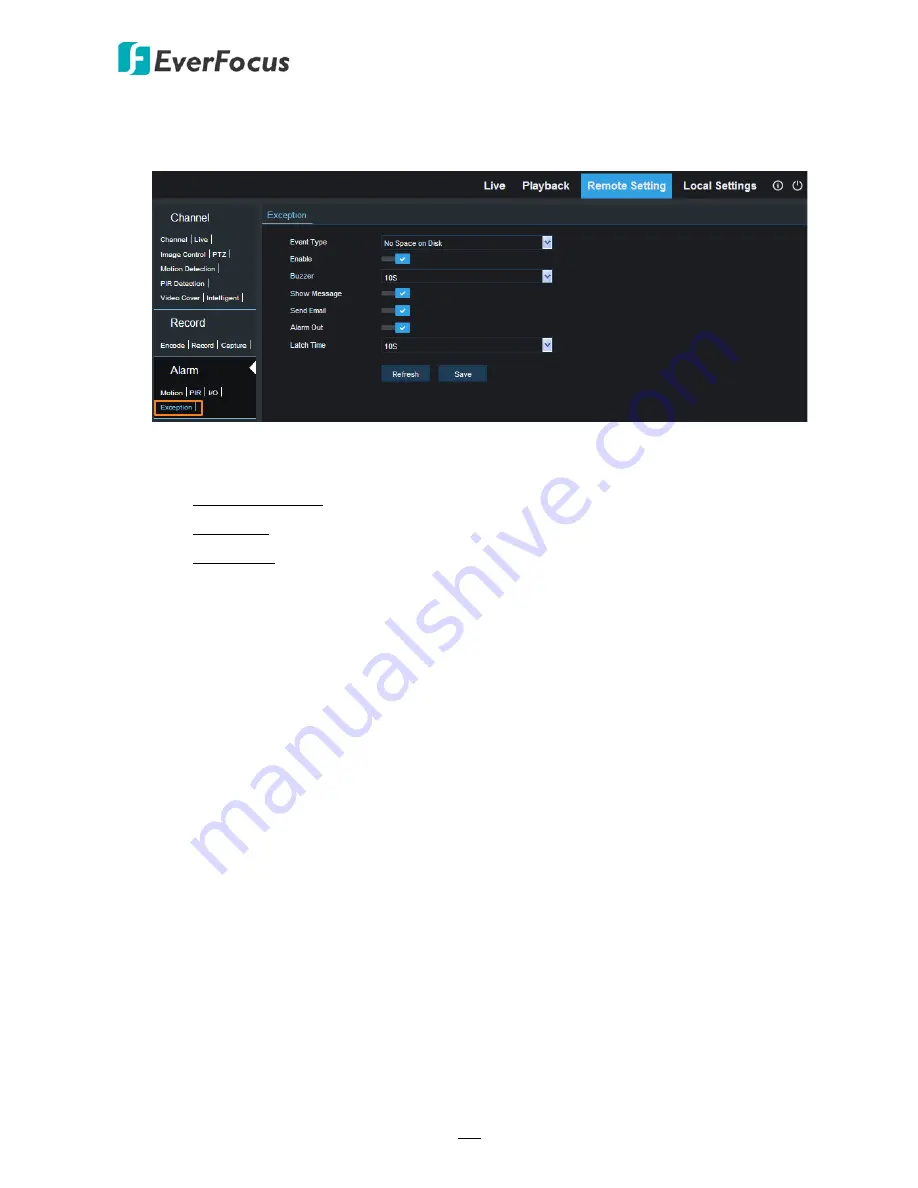
5.4.3.4 Exception
You can configure the system alarm settings on this page.
Event Type:
Select an event type.
•
No Space on Disk: When an HDD is full.
•
Disk Error: When the HDD is not detected properly.
•
Video Loss: When a camera is not connected properly.
Enable:
Switch the button to the right to enable this function.
Buzzer:
Select a time for DVR buzzer to sound when an alarm is triggered. Select
Disable
to
disable the function.
Show Message:
Switch the button to the right to enable displaying system alarm icon “S” on
the live channel when an alarm is triggered.
Send Email:
Switch the button to the right to enable the Email alert function. When an alarm
is triggered, the DVR will send an email alert with a snapshot to the pre-configured Email
receiver. Note that for this function to work, you have to set up the Email function in
advance (refer to
5
.
4.4.3 Email
).
Alarm Out:
Check the box to enable the connected external alarm output device.
Latch Time:
Select an alarm output time (duration) when events occur. When an event is
triggered, the alarm will last based on the setup latch time.
Click
Save
to save the settings or
Refresh
to refresh the page.


