330-In
stal_Electr sw1
13.fm
- 29/4/21
INSTALLATION - ELECTRICAL
30
Installation guide
7
ACCESSORY CONNECTIONS
Activators
The following types of devices can be installed: radar
motion sensors, passive infrared motion sensors, push
buttons, switches, radio, IR receivers, access control
systems, telephone and intercom systems, etc.
Minimum requirements:
•
Service voltage supplied by the drive unit: 24V DC
±5%
•
Impulse duration: Min. 200 ms.
•
Voltage free output
•
Energised output (telephone systems): Max. 24 V
DC / AC ±5%.
The activators can be connected as:
•
Activation
Æ
INTERNAL
-
Normal Activation
Æ
normal speeds and
opening time
-
Courtesy Activation
Æ
speeds and courtesy
opening time
•
Activation
Æ
EXTERNAL
-
Normal Activation
Æ
normal speeds and
opening time
-
Courtesy Activation
Æ
speeds and courtesy
opening time
Do not connect the power to the signal input!
On double doors the sensors must be installed on
the Master board.
Safety sensors
Closing surveillance
: Fit the sensor (SIS) on the door.
•
When the sensor is enabled in the closing
movement, the door stops and reverses at normal
speed.
Opening surveillance
: Fit the sensor (SIO) on the
door.
•
The door stops when the sensor is enabled in the
opening movement. If the sensor (SIO) is disabled,
the door continues the opening operation at slow
speed until it finishes, or the sensor detects presence
again. Once open, it closes in normal movement.
DIN1865, EN16005
The safety sensors (SIS) installed must have a
test input to monitor correct operation. In
consequence, input will be configured by
defect to enable the test "with test" before
each opening operation, and also in NC mode
(normally closed). Enter configuration in the
Tech. Support menu if this input needs to be
modified.
On double doors, the safety sensors must each be
connected to their electronic board (Master Gate to
the Master board / Slave Gate to the Slave board).
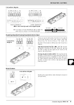
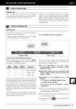
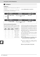
Connections diagram:
INSIDE SENSOR
OUTSIDE SENSOR

