330-In
stalacion sw113.fm
- 29/4
/21
INSTALLATION
12
Installation guide
5
OPERATOR INSTALLATION
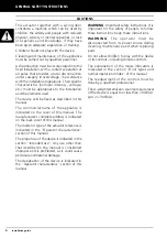
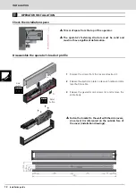
Check the installation space
Disassemble the operator's bracket profile
M
in
imu
m d
is
ta
n
c
e
1
0
mm
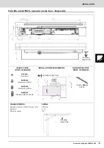
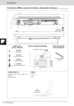
10 mm of space from the top of the operator.
The operator's fastening structure must be solid and
must not have significant deformation.
If the wall where the operator is to be secured is not strong and
reliable, a drilled metal plate can be provided on request to
36 37 38
14 15
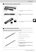
1
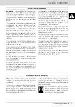
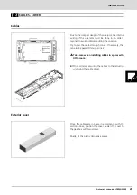
Remove the screws from the cover and extract it.
2
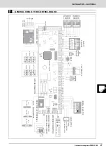
Release the electronic plate's side switch cable and side
reset button cable.
3
Release the geared motor screws (4) and remove the
entire body.
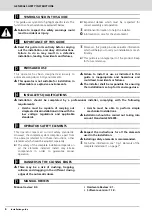
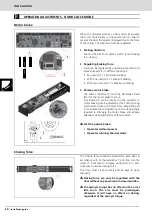
Fasten the bracket to the wall with the side covers,
since level X is referenced on the outside face of
the cover (installation drawings).
Side
switch
Reset
button


