330-In
stal_Electr sw1
13.fm
- 29/4/21
INSTALLATION - ELECTRICAL
32
Installation guide
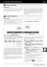
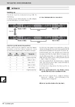
Locking devices
Four parameters must be specified when configuring a
locking device:
1 Type of device
-
Specific power supply device configuration
(intercom)
-
Continuous power supply device configuration
2 Voltage
-
12 VDC
-
24 VDC
3 Opening delay
This is the time delay between lock activation and
the start of the door's opening movement. It is
configured in seconds (between 1 and 10 sec.). It is
a common parameter for all devices and must be
configured according to the characteristics of each
device.
4 Test
This is the type of signal the electrical lock uses to
indicate its status:
-
NA
-
NC
-
OFF (test disabled)
In order to guarantee safe operation of the drive unit,
t h e l o c k i n g d e v i c e m u s t m e e t t h e f o l l o w i n g
specifications:
•
Service voltage supplied by the drive unit:
24V DC/AC ±5% / 12V DC/AC ±5%
•
Service voltage with external power:
max. 230 V DC/AC ±5%
•
Contact relay locking load: max. 2A
The operator automatically makes a movement
against the latch to help release the lock on each
a c t i v a t i o n . T h e f o r c e o f t h i s m o v e m e n t i s
proportional to the delay time.
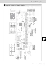
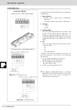
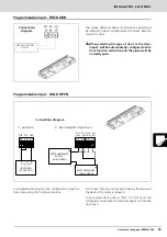
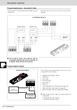
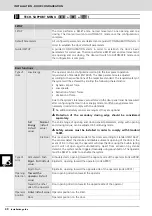
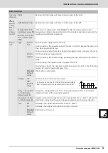
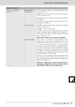
Connections diagram
ELECTRO LOCK - BY EXTERNAL POWER
ELECTRO LOCK - POWER DOOP SWING
ELECTRO LOCK (NO) - EXTERNAL POWER
ELECTRO LOCK (NC) - EXTERNAL POWER
EXTERNAL
POWER SUPPLY
EXTERNAL
POWER SUPPLY
POWER OFF
IN CLOSE/OPEN POSITION!
POWER ON
IN CLOSE/OPEN POSITION!


