EPSON Stylus Pro 4400/4450/4800/4880/4880C
Revision C
Adjustment
Basic Adjustment
399
6.
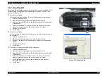
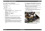
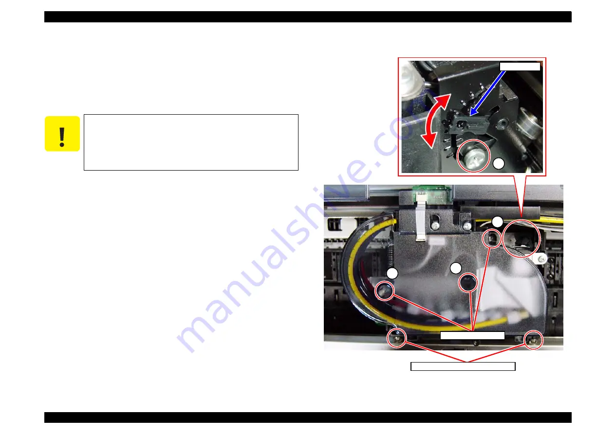
Open the top cover and loosen the two screws that secure the
"Stopper, Carriage" shown in
7.
Loosen the four head fixing screws (A, B, C, and D) shown in
.
8.
Move the "Lever, Cam" vertically and adjust the slant of the print head.
z
Gap on the left column
: Lower the "Lever, Cam".
z
Gap on the right column : Raise the "Lever, Cam".
9.
Tighten the four screws that have been loosened in
in the
order A ->B ->C ->D.
10. Secure the two screws that secure the "Stopper, Carriage", and close
the top cover. (The "Carriage Unit" moves to its home position.)
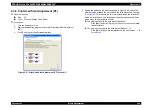
11. Click [Back] twice to go back to Screen 1, and click [Print] to print the
adjustment pattern. (Once the printing is finished, the "Carriage Unit"
moves to the center of the printer (adjustment position).)
12. Click [Next]. (Proceed to Screen 2.)
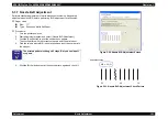
13. Seeing the pattern in the direction shown in
, check the
clearance gap between the light magenta and magenta for both right
and left columns of the third, ninth, and fifteenth blocks from the right.
z
No gap on both sides:No adjustment required ->Proceed to
.
z
Gap on any of the sides:Adjustment required -> Proceed to
Figure 5-37. Head Fixing Screws and Lever, Cam
C A U T I O N
The position of the "Lever, Cam" can only be adjusted by
moving downward. When you need to raise the "Lever,
Cam", raise it to the upper limit first and lower the
"Lever, Cam" gradually.
Make sure to move the "Lever, Cam" while pressing it
rearward, or the adjustment groove may be damaged.
A
B
C
Lever, Cam
D
Stopper, Carriage Fixing Screws
Head Fixing Screws
Summary of Contents for Stylus Pro 4800 Portrait Edition
Page 9: ...C H A P T E R 1 PRODUCTDESCRIPTION ...
Page 113: ...C H A P T E R 2 OPERATINGPRINCIPLES ...
Page 156: ...C H A P T E R 3 TROUBLESHOOTING ...
Page 200: ...C H A P T E R 4 DISASSEMBLY ASSEMBLY ...
Page 366: ...C H A P T E R 5 ADJUSTMENT ...
Page 448: ...C H A P T E R 6 MAINTENANCE ...
Page 457: ...C H A P T E R 7 APPENDIX ...

