EPSON Stylus Pro 4400/4450/4800/4880/4880C
Revision C
Adjustment
Basic Adjustment
390
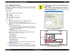
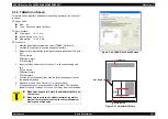
5.3.4 T&B&S (Roll Paper)
This adjusts the printing position that includes the cut position on the surface of
the paper and corrects a bend of emission axis of the main scanning direction
in the multi sensor.
Paper Used
Size: 17"
Type: Enhanced Matte Roll Paper
Specifications
Top margin:
10 ± 1 mm
Bottom margin: 114 ± 1 mm
Side margin:
10 ± 0.3 mm
Procedure
1.
Start adjustment program and select [T&B&S (Roll Paper)].
2.
Click the [Print] button to print the adjustment pattern.
3.
Refer to
, and measure the distance of the following three
positions;
Top margin, bottom margin
Check the arrow direction of "T&B Position" printed on the pattern.
Then measure the distances of margins indicated with arrows in
for top and bottom.
Side margin
Measure the distance as shown in
4.
Input each of the following value into its corresponding edit boxes.
Top margin
Bottom margin
Side margin
The values printed in the pattern lower part
Multi sensor left
Multi sensor right
5.
Click the [Write] button and then click the [Print] button again to print
the adjustment pattern.
6.
Repeat
and
, and click [Write].
7.
If the specification values are satisfied, click [Finish]. If not satisfied,
repeat
through
until they meet the standards.
.
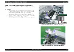
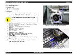
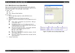
Figure 5-24. T&B&S (Roll Paper)
Figure 5-25. Adjustment Pattern
C A U T I O N
When measuring colors, place the adjustment pattern on
a flat surface.
Make sure to perform the adjustment twice regardless
whether the value obtained from the first measurement
meets the specified value.
T&B Position : <-- MS Left : XX.XXX mm MS Right : XX.XXX mm
T & B Position : <
MS Left : XX.XXX mm
MS Right : X.XXX mm
--
Top Margin
(->)
Top Margin
(<-)
Bottom Margin
(->)
Bottom Margin
(<-)
Side Margin
Summary of Contents for Stylus Pro 4800 Portrait Edition
Page 9: ...C H A P T E R 1 PRODUCTDESCRIPTION ...
Page 113: ...C H A P T E R 2 OPERATINGPRINCIPLES ...
Page 156: ...C H A P T E R 3 TROUBLESHOOTING ...
Page 200: ...C H A P T E R 4 DISASSEMBLY ASSEMBLY ...
Page 366: ...C H A P T E R 5 ADJUSTMENT ...
Page 448: ...C H A P T E R 6 MAINTENANCE ...
Page 457: ...C H A P T E R 7 APPENDIX ...


