EPSON AcuLaser C4000/C4100/C3000
Revision F
Appendix
Wiring Diagrams and Signal Information
9-649
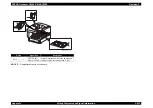
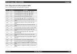
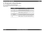
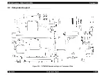
9.6.3 Notation on the Diagrams for the Wiring and
Signal Descriptions between Components
The symbols used in the wiring connection diagrams for parts on the following
pages are as follows. Explanations of commonly used symbols are omitted.
Symbol
Description
Shows a plug (female connector).
Shows a jack (male connector).
Shows Pin yy and Jack yy for Pxx/Jxx
connector.
Shows a part.
The "PL x.y.z" number refers to Section 9.4.2
"Parts List Tables", Plate (PL) number 'x.y',
item number 'z'.
Shows a part's internal component, with the
name of that component.
Shows the PWB's internal CONTROLLER,
with its outline.
Shows harness/wire connections between
components, with the signal name/content.
The arrow shows signal direction.
P/J
XX
YY
PWB DRIVE
PL X.Y.Z
Heater
Control
DEVE_A
Shows a signal's logic value (Low: L or High:
H) when a function's motion has been
activated. The voltage shown is the signal
strength at High condition.
The arrow shows signal direction.
Shows a signal's logic value (Low: L or High:
H) when function's condition has been
detected. The voltage shown is the signal
strength at High condition.
The arrow shows signal direction.
Shows wiring connections.
I/L +24VDC
Shows DC voltage when the Interlock Switch
of the PWBA MCU & HVPS is ON.
+5VDC
+3.3VDC
Shows DC voltage.
SG
Indicates signal ground.
AG
Indicates analog ground.
RTN
Indicates return.
Symbol
Description
REGI CLUTCH ON(L)+24VDC
EXIT PAPER SENSED(L)+3.3VDC
Summary of Contents for AcuLaser C3000 Series
Page 20: ...C H A P T E R 1 PRODUCTDESCRIPTIONS ...
Page 71: ...C H A P T E R 2 OPERATINGPRINCIPLES ...
Page 118: ...C H A P T E R 3 TROUBLESHOOTING ...
Page 318: ...C H A P T E R 4 DISASSEMBLYANDASSEMBLY ...
Page 472: ...C H A P T E R 5 ADJUSTMENT ...
Page 477: ...C H A P T E R 6 MAINTENANCE ...
Page 491: ...C H A P T E R 7 AcuLaserC4100 ...
Page 548: ......
Page 549: ......
Page 550: ......
Page 551: ......
Page 552: ......
Page 553: ......
Page 554: ......
Page 555: ...C H A P T E R 8 AcuLaserC3000 ...
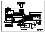
Page 579: ...Model AcuLaser C3000 Board C569MAIN BOARD Sheet 1 of 5 Rev B ...
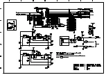
Page 580: ...Model AcuLaser C3000 Board C569MAIN BOARD Sheet 2 of 5 Rev B ...
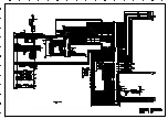
Page 581: ...Model AcuLaser C3000 Board C569MAIN BOARD Sheet 3 of 5 Rev B ...
Page 582: ...Model AcuLaser C3000 Board C569MAIN BOARD Sheet 4 of 5 Rev B ...
Page 583: ...Model AcuLaser C3000 Board C569MAIN BOARD Sheet 5 of 5 Rev B ...
Page 584: ...C H A P T E R 9 APPENDIX ...
Page 674: ......
Page 675: ......
Page 676: ......
Page 677: ......
Page 678: ......
Page 679: ......
Page 680: ......


