EPSON AcuLaser C4000/C4100/C3000
Revision F
Troubleshooting
Level 2 FIP
3-147
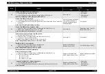
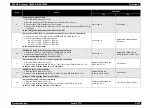
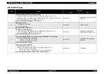
FIP-11 Regi Jam
Step
Check
Treatment
Yes
No
1
Initial setting
Do the following checks show a problem?
• Actuator Regi (PL10.1.21) installation
• Sensor Regi (PL10.1.20) installation
• Chute Assy Regi (PL10.1.1) installation
Reinstall applicable parts.
Go to step 2.
2
Is the paper in tray 1/2/3 and the tray Assy MSI (PL1.2.12) normal with no curl, wrinkles
or moisture?
Go to step 3.
Replace the paper and go to
step 3.
3
Paper feed path
Check the paper feed path.
Are there any foreign particles in the paper feed path?
Go to step 4.
Remove the foreign particles
and go to step 4.
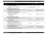
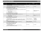
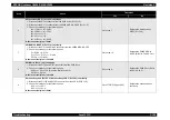
4
Carry out a test print.
Does the problem still occur?
• With the tool: Go to step 5.
• Without the tool: Go to step 6.
Problem solved.
5
Sensor Regi (PL10.1.20) check
Use the Sensor Regi diagnosis tool to carry out a Digital Input Test.
Is the Sensor Regi functioning normally?
Go to step 13.
Go to step 6.
6
Clutch Regi (PL10.1.12) harness connection check
1. Remove the Chute Assy Regi. (Refer to Ch4-4.2.13.1)
2. Check the connection of the Sensor Regi (PL10.1.20) P/J181 connector.
Is the continuity between P/J181 normal?
Go to step 7.
Reinstall applicable parts.
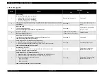
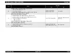
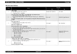
7
Actuator Regi (PL10.1.21)
Operate and release the actuator regi manually and monitor the operation.
Does the Actuator Regi move smoothly?
Go to step 8.
Replace the Actuator Regi.
(Refer to Ch4-4.2.13.3)
8
Clutch Regi (PL10.1.12) Harness continuity
1. Disconnect the P/J18 connector from the PWBA MCU & HVPS (PL15.1.2).
2. Disconnect the P/J181 connector from the PWB Drive (PL10.1.20).
3. Check the continuity for the following lines.
J181-1 <=> J18-3
J181-2 <=> J18-2
J181-3 <=> J18-1
Is the continuity between J181 <=> J18 normal?
Go to step 9.
Replace the Chute Assy Regi.
(Refer to Ch4-4.2.13.1)
Summary of Contents for AcuLaser C3000 Series
Page 20: ...C H A P T E R 1 PRODUCTDESCRIPTIONS ...
Page 71: ...C H A P T E R 2 OPERATINGPRINCIPLES ...
Page 118: ...C H A P T E R 3 TROUBLESHOOTING ...
Page 318: ...C H A P T E R 4 DISASSEMBLYANDASSEMBLY ...
Page 472: ...C H A P T E R 5 ADJUSTMENT ...
Page 477: ...C H A P T E R 6 MAINTENANCE ...
Page 491: ...C H A P T E R 7 AcuLaserC4100 ...
Page 548: ......
Page 549: ......
Page 550: ......
Page 551: ......
Page 552: ......
Page 553: ......
Page 554: ......
Page 555: ...C H A P T E R 8 AcuLaserC3000 ...
Page 579: ...Model AcuLaser C3000 Board C569MAIN BOARD Sheet 1 of 5 Rev B ...
Page 580: ...Model AcuLaser C3000 Board C569MAIN BOARD Sheet 2 of 5 Rev B ...
Page 581: ...Model AcuLaser C3000 Board C569MAIN BOARD Sheet 3 of 5 Rev B ...
Page 582: ...Model AcuLaser C3000 Board C569MAIN BOARD Sheet 4 of 5 Rev B ...
Page 583: ...Model AcuLaser C3000 Board C569MAIN BOARD Sheet 5 of 5 Rev B ...
Page 584: ...C H A P T E R 9 APPENDIX ...
Page 674: ......
Page 675: ......
Page 676: ......
Page 677: ......
Page 678: ......
Page 679: ......
Page 680: ......


