EPSON AcuLaser C4000/C4100/C3000
Revision F
Troubleshooting
Overview
3-104
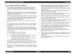
3.1.3 Precautions When Performing Work
1. Be sure to unplug the POWER CORD (PL15.1.9) except when necessary
when performing work.
2. When carrying out work with the covers off, the interlock and safety switches
on and the power turned on, make sure that you disconnect the connector (P/
J151) of the ROS Assy (PL11.1.1) or remove the PHD Assy (PL11.1.3) to
prevent laser radiation from being emitted, particularly when these
components are not needed.
3. When carrying out work with the left cover removed and the power turned on,
make sure that you disconnect the connector (P/J5011) of the HVPS SUB
board (PL12.1.9), particularly when this component is not needed.
4. Be careful to avoid harmful burns when touching parts that may be hot.
5. When carrying out work, you should use a wrist band to ground your body in
order to eliminate static electricity from your body.
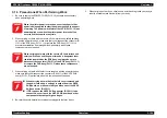
W A R N I N G
When the printer power is turned on, never touch parts that
power is being applied to other than when required to as a part
of working. The power switch/inlet of the LVPS (PL15.1.10) has
power applied even when the printer power is turned off, so
never touch these parts at any time.
W A R N I N G
When carrying out work with the covers off, the interlock and
safety switches on and the power turned on, dangerous laser
radiation is emitted by the ROS Assy, so always be sure to
disconnect the connector (P/J151) of the ROS Assy (PL11.1.1)
or remove the PHD Assy (PL11.1.3) when these components
are not needed.
W A R N I N G
When carrying out work with the left cover removed and
the power turned on, a voltage is output from the HVPS
SUB board, so make sure that you disconnect the HVPS
SUB connector (P/J5011).
If FIP requires the HVPS SUB connector (P/J5011) to be
connected, never touch the HVPS SUB board and other
components that output high voltages.
Summary of Contents for AcuLaser C3000 Series
Page 20: ...C H A P T E R 1 PRODUCTDESCRIPTIONS ...
Page 71: ...C H A P T E R 2 OPERATINGPRINCIPLES ...
Page 118: ...C H A P T E R 3 TROUBLESHOOTING ...
Page 318: ...C H A P T E R 4 DISASSEMBLYANDASSEMBLY ...
Page 472: ...C H A P T E R 5 ADJUSTMENT ...
Page 477: ...C H A P T E R 6 MAINTENANCE ...
Page 491: ...C H A P T E R 7 AcuLaserC4100 ...
Page 548: ......
Page 549: ......
Page 550: ......
Page 551: ......
Page 552: ......
Page 553: ......
Page 554: ......
Page 555: ...C H A P T E R 8 AcuLaserC3000 ...
Page 579: ...Model AcuLaser C3000 Board C569MAIN BOARD Sheet 1 of 5 Rev B ...
Page 580: ...Model AcuLaser C3000 Board C569MAIN BOARD Sheet 2 of 5 Rev B ...
Page 581: ...Model AcuLaser C3000 Board C569MAIN BOARD Sheet 3 of 5 Rev B ...
Page 582: ...Model AcuLaser C3000 Board C569MAIN BOARD Sheet 4 of 5 Rev B ...
Page 583: ...Model AcuLaser C3000 Board C569MAIN BOARD Sheet 5 of 5 Rev B ...
Page 584: ...C H A P T E R 9 APPENDIX ...
Page 674: ......
Page 675: ......
Page 676: ......
Page 677: ......
Page 678: ......
Page 679: ......
Page 680: ......

