EPSON AcuLaser C4000/C4100/C3000
Revision F
Troubleshooting
Level 2 FIP
3-201
7
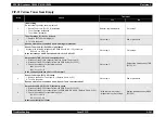
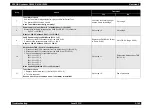
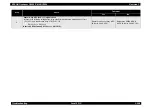
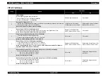
Toner Motor check
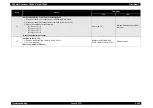
Use the Toner Motor diagnosis tool to carry out a Digital Output Test.
The Interlock SW should be closed.
Is the Toner Motor functioning normally?
Check the toner mixing Auger
and the Gears for damage. If
there is damaged part, replace
the applicable part and if there is
nothing, replace the PWBA
MCU & HVPS.
Go to step 8.
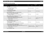
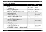
8
Power supply to Toner Motor (K) of Holder Assy (K) (PL12.2.8)
Measure the following voltages at the PWB Drive (PL15.1.15) connector.
P/J51-24 <=> P/J60-2
Is there +24V DC between P/J51-24 <=> P/J60-2.
Go to step 10.
Go to step 9.
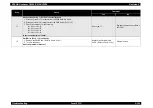
9
24V DC power supply to PWB Drive (PL15.1.15)
1. Disconnect the P/J60 connector from the PWB Drive.
2. Measure the voltage between J60-1 <=> J60-2.
Is there +24V DC between J60-1 <=> J60-2?
Replace the PWB Drive.
(Refer to Ch4-4.2.18.5)
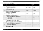
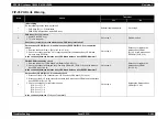
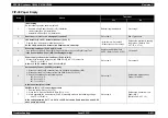
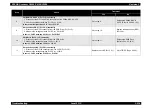
10
Harness Assy TNR (PL12.1.6) continuity check
1. Disconnect the P/J514 connector from the Holder Assy (K) (PL12.2.8).
2. Disconnect the P/J51 connector from the PWB Drive (PL15.1.15).
3. Check the continuity for the following lines.
J514-1 <=> J51-28
J514-2 <=> J51-27
J514-3 <=> J51-26
J514-4 <=> J51-25
J514-5 <=> J51-24
Is the continuity between J514 <=> J51 normal?
Go to step 11.
Replace the Harness Assy TNR
(PL12.1.6).
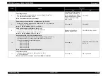
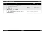
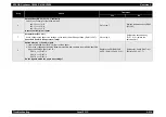
11
Toner Motor check
1. Replace the Holder Toner Assy (K). (Refer to Ch4-4.2.15.5)
2. Turn On the power.
Does an error occur even when a new Toner Motor is installed?
Go to step 12.
End of procedure
Step
Check
Treatment
Yes
No
Summary of Contents for AcuLaser C3000 Series
Page 20: ...C H A P T E R 1 PRODUCTDESCRIPTIONS ...
Page 71: ...C H A P T E R 2 OPERATINGPRINCIPLES ...
Page 118: ...C H A P T E R 3 TROUBLESHOOTING ...
Page 318: ...C H A P T E R 4 DISASSEMBLYANDASSEMBLY ...
Page 472: ...C H A P T E R 5 ADJUSTMENT ...
Page 477: ...C H A P T E R 6 MAINTENANCE ...
Page 491: ...C H A P T E R 7 AcuLaserC4100 ...
Page 548: ......
Page 549: ......
Page 550: ......
Page 551: ......
Page 552: ......
Page 553: ......
Page 554: ......
Page 555: ...C H A P T E R 8 AcuLaserC3000 ...
Page 579: ...Model AcuLaser C3000 Board C569MAIN BOARD Sheet 1 of 5 Rev B ...
Page 580: ...Model AcuLaser C3000 Board C569MAIN BOARD Sheet 2 of 5 Rev B ...
Page 581: ...Model AcuLaser C3000 Board C569MAIN BOARD Sheet 3 of 5 Rev B ...
Page 582: ...Model AcuLaser C3000 Board C569MAIN BOARD Sheet 4 of 5 Rev B ...
Page 583: ...Model AcuLaser C3000 Board C569MAIN BOARD Sheet 5 of 5 Rev B ...
Page 584: ...C H A P T E R 9 APPENDIX ...
Page 674: ......
Page 675: ......
Page 676: ......
Page 677: ......
Page 678: ......
Page 679: ......
Page 680: ......

