EPSON AcuLaser C4000/C4100/C3000
Revision F
Troubleshooting
Level 2 FIP –Large Capacity Paper Unit–
3-288
27
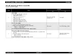
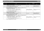
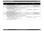
Clutch Assy Turn TRAY 3 (PL17.3.18) resistance check
1. Disconnect the P/J835 connector from the Clutch Assy Turn TRAY 3 (PL17.3.18). (Refer
2. Measure the resistance between J835-1 <=> J835-2.
Is the resistance 200
Ω
between J835-1 <=> J835-2?
Replace the PWBA MCU &
HVPS. (Refer to Ch4-4.2.18.1)
Replace the Clutch Assy Turn
TRAY 3.
(Refer to Ch4-4.2.20.30)
28
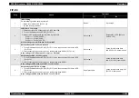
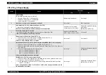
Solenoid Feed TRAY 3 (PL17.3.17) operation check
1. Print a single page while feeding paper from the TRAY 3.
2. Check if the leading edge of the paper is fed from the Cassette Assy (PL2.1.4).
Is the paper fed from the Cassette Assy when a single page is printed?
Check that no parts are missing.
If all parts are okay, replace the
paper and replace the PWBA
MCU & HVPS.
(Refer to Ch4-4.2.18.1)
• With the tool:
Go to step 29.
• Without the tool:
Go to step 30.
29
Solenoid Feed TRAY 3 (PL17.3.17) check
Use the Solenoid Feed TRAY 3 diagnosis tool to carry out a Digital Output Test.
The INTERLOCK SW should be closed.
Solenoid Feed TRAY 3 functioning normally?
Check if the Solenoid Feed
(PL17.3.17) spring or stopper is
loose.
Go to step 30.
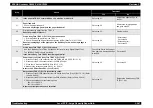
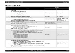
30
Power supply to Solenoid Feed TRAY 3 (PL17.3.17)
1. Disconnect the P/J140 connector from the PWBA MCU & HVPS (PL15.1.2).
2. Disconnect the P/J83 connector from the PWBA Feeder.
3. Close the I/L Switch of the PWB Drive (PL15.1.15).
4. Measure the voltage between P83-11 <=> P/J81-1.
Is there +24V DC between P83-11 <=> P/J81-1?
Go to step 31.
Go to step 33.
31
Harness Assy FDR 3T (PL17.4.4) continuity check
1. Disconnect the P/J834 connector from the Solenoid Feed (Tray 3) (PL17.3.17). (Refer to
2. Disconnect the P/J83 connector from the PWBA Feeder. (Refer to Ch4-4.2.20.10)
3. Check the continuity for the following lines.
J83-11 <=> P834-2
J83-12 <=> P834-1
Is there continuity between each terminal?
Go to step 32.
Replace the Harness Assy FDR
3T (PL17.4.4).
32
Solenoid Feed TRAY 3 (PL17.3.17) resistance check
1. Disconnect the J834 connector from the Solenoid Feed (Tray 3). (Refer to Ch4-4.2.20.22)
2. Measure the resistance between J834-1 <=> J834-2.
Is the resistance 100
Ω
between J834-1 <=> J834-2?
Replace the PWBA MCU &
HVPS. (Refer to Ch4-4.2.18.1)
Replace the Solenoid Feed
TRAY 3.
(Refer to Ch4-4.2.20.22)
Step
Check
Treatment
Yes
No
Summary of Contents for AcuLaser C3000 Series
Page 20: ...C H A P T E R 1 PRODUCTDESCRIPTIONS ...
Page 71: ...C H A P T E R 2 OPERATINGPRINCIPLES ...
Page 118: ...C H A P T E R 3 TROUBLESHOOTING ...
Page 318: ...C H A P T E R 4 DISASSEMBLYANDASSEMBLY ...
Page 472: ...C H A P T E R 5 ADJUSTMENT ...
Page 477: ...C H A P T E R 6 MAINTENANCE ...
Page 491: ...C H A P T E R 7 AcuLaserC4100 ...
Page 548: ......
Page 549: ......
Page 550: ......
Page 551: ......
Page 552: ......
Page 553: ......
Page 554: ......
Page 555: ...C H A P T E R 8 AcuLaserC3000 ...
Page 579: ...Model AcuLaser C3000 Board C569MAIN BOARD Sheet 1 of 5 Rev B ...
Page 580: ...Model AcuLaser C3000 Board C569MAIN BOARD Sheet 2 of 5 Rev B ...
Page 581: ...Model AcuLaser C3000 Board C569MAIN BOARD Sheet 3 of 5 Rev B ...
Page 582: ...Model AcuLaser C3000 Board C569MAIN BOARD Sheet 4 of 5 Rev B ...
Page 583: ...Model AcuLaser C3000 Board C569MAIN BOARD Sheet 5 of 5 Rev B ...
Page 584: ...C H A P T E R 9 APPENDIX ...
Page 674: ......
Page 675: ......
Page 676: ......
Page 677: ......
Page 678: ......
Page 679: ......
Page 680: ......


