EPSON AcuLaser C4000/C4100/C3000
Revision F
Troubleshooting
Level 2 FIP
3-161
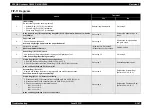
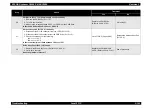
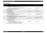
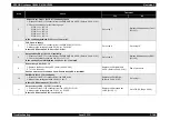
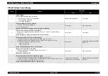
FIP-15 Fuser Failure
Step
Check
Treatment
Yes
No
1
Initial setting
Do the following checks show a problem?
• Fuser Assy (PL9.1.1) installation
Reinstall applicable parts.
Go to step 2.
2
Fuser Assy (PL9.1.1) and Harness Assy FSR2 (PL6.1.9) connector check
1. Remove the Fuser Assy. (Refer to Ch4-4.2.12.1)
2. Check if there are any broken or bent terminals in the Fuser Assy and Harness Assy
FSR2.
Are any of the terminals in the Fuser Assy and Harness Assy FSR2 connectors bent or
broken?
Go to step 3.
Replace the applicable parts.
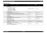
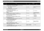
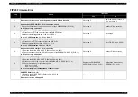
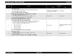
3
Fuser Assy (PL9.1.1)
1. Replace the Fuser Assy. (Refer to Ch4-4.2.12.1)
2. Turn On the power.
Does the error still occur?
Go to step 4.
End of procedure
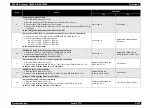
4
Harness Assy FSR 2 (PL6.1.9) continuity
1. Remove the Fuser Assy. (Refer to Ch4-4.2.12.1)
2. Disconnect the P/J138 relay connector between the Harness Assy Front 1 (PL15.2.7) and
the Harness Assy FSR2.
3. Disconnect the P/J162 connector from the LVPS (PL15.1.10).
4. Check the continuity for the following lines.
J232-A2 <=> P138-4
J232-A1 <=> P138-5
J232-3 <=> J162-2
J232-1 <=> J162-1
Is there continuity in all lines?
Go to step 5.
Replace the Harness Assy
FSR2 (PL 6.1.9).
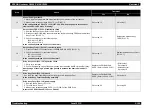
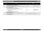
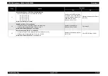
5
Harness Assy Front 1 (PL15.2.7) continuity
1. Disconnect the P/J13 connector from the PWBA MCU & HVPS (PL15.1.2).
2. Check the continuity for the following lines.
J138-5 <=> J13-17
J138-4 <=> J13-18
Is there continuity in all lines?
Go to step 6.
Replace the Harness Assy Front 1
(PL15.2.7).
Summary of Contents for AcuLaser C3000 Series
Page 20: ...C H A P T E R 1 PRODUCTDESCRIPTIONS ...
Page 71: ...C H A P T E R 2 OPERATINGPRINCIPLES ...
Page 118: ...C H A P T E R 3 TROUBLESHOOTING ...
Page 318: ...C H A P T E R 4 DISASSEMBLYANDASSEMBLY ...
Page 472: ...C H A P T E R 5 ADJUSTMENT ...
Page 477: ...C H A P T E R 6 MAINTENANCE ...
Page 491: ...C H A P T E R 7 AcuLaserC4100 ...
Page 548: ......
Page 549: ......
Page 550: ......
Page 551: ......
Page 552: ......
Page 553: ......
Page 554: ......
Page 555: ...C H A P T E R 8 AcuLaserC3000 ...
Page 579: ...Model AcuLaser C3000 Board C569MAIN BOARD Sheet 1 of 5 Rev B ...
Page 580: ...Model AcuLaser C3000 Board C569MAIN BOARD Sheet 2 of 5 Rev B ...
Page 581: ...Model AcuLaser C3000 Board C569MAIN BOARD Sheet 3 of 5 Rev B ...
Page 582: ...Model AcuLaser C3000 Board C569MAIN BOARD Sheet 4 of 5 Rev B ...
Page 583: ...Model AcuLaser C3000 Board C569MAIN BOARD Sheet 5 of 5 Rev B ...
Page 584: ...C H A P T E R 9 APPENDIX ...
Page 674: ......
Page 675: ......
Page 676: ......
Page 677: ......
Page 678: ......
Page 679: ......
Page 680: ......

