EPSON AcuLaser C4000/C4100/C3000
Revision F
Troubleshooting
Level 2 FIP
3-173
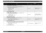
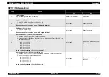
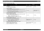
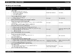
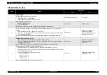
FIP-22 Yellow Toner Empty
Step
Check
Treatment
Yes
No
1
Initial setting
Do the following checks show a problem?
• Sensor Toner Low (PL12.2.9) installation
• Toner Cartridge installation
• Toner Motor installation
Reinstall applicable parts.
Go to step 2.
2
Toner Cartridge (Y) (PL12.1.1) check
1. Replace the Toner Cartridge (Y).
2. Turn On the power.
Does an error occur even when a new Cartridge is installed?
Go to step 3.
End of procedure
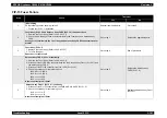
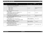
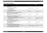
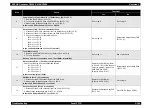
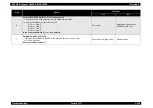
3
Sensor Toner Low (Y) (PL12.2.9) signal check
Measure the voltage between connectors P/J51-16 <=> P/J51-15 of the PWB Drive
(PL15.1.15).
Is the resi 0.2V DC between P/J51-16 <=> P/J51-15?
Go to step 6.
Go to step 4.
4
Harness Assy TNR (PL12.1.6) continuity check
1. Disconnect the P/J51 connector from the PWB Drive (PL15.1.15).
2. Disconnect the P/J441 connector from the Sensor Toner Low (PL12.2.9) (Y).
3. Check the continuity for the following lines.
J441-2 <=> J51-16
J441-3 <=> J51-15
Is the continuity between J441 <=> J51 normal?
Go to step 5.
Replace the Harness Assy TNR
(PL12.1.6).
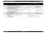
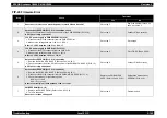
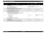
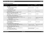
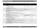
5
Sensor Toner Low (PL12.2.9) check
1. Replace the Sensor Toner Low. (Refer to Ch4-4.2.15.7)
2. Turn On the power.
Does the error still occur?
Go to step 6.
End of procedure
6
Harness Assy DRV 2 (PL15.2.3) continuity check
1. Disconnect the P/J42 connector from the PWB Drive (PL15.1.15).
2. Disconnect the P/J12 connector from the PWBA MCU & HVPS. (Refer to Ch4-4.2.18.1)
3. Check the continuity between J12-23 <=> J42-8.
Is the continuity between J12-23 <=> J42-8 normal?
• With the tool: Go to step 7.
• Without the tool: Go to step 8.
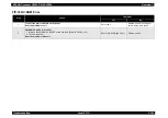
Replace the Harness Assy DRV 2
(PL15.2.3).
Summary of Contents for AcuLaser C3000 Series
Page 20: ...C H A P T E R 1 PRODUCTDESCRIPTIONS ...
Page 71: ...C H A P T E R 2 OPERATINGPRINCIPLES ...
Page 118: ...C H A P T E R 3 TROUBLESHOOTING ...
Page 318: ...C H A P T E R 4 DISASSEMBLYANDASSEMBLY ...
Page 472: ...C H A P T E R 5 ADJUSTMENT ...
Page 477: ...C H A P T E R 6 MAINTENANCE ...
Page 491: ...C H A P T E R 7 AcuLaserC4100 ...
Page 548: ......
Page 549: ......
Page 550: ......
Page 551: ......
Page 552: ......
Page 553: ......
Page 554: ......
Page 555: ...C H A P T E R 8 AcuLaserC3000 ...
Page 579: ...Model AcuLaser C3000 Board C569MAIN BOARD Sheet 1 of 5 Rev B ...
Page 580: ...Model AcuLaser C3000 Board C569MAIN BOARD Sheet 2 of 5 Rev B ...
Page 581: ...Model AcuLaser C3000 Board C569MAIN BOARD Sheet 3 of 5 Rev B ...
Page 582: ...Model AcuLaser C3000 Board C569MAIN BOARD Sheet 4 of 5 Rev B ...
Page 583: ...Model AcuLaser C3000 Board C569MAIN BOARD Sheet 5 of 5 Rev B ...
Page 584: ...C H A P T E R 9 APPENDIX ...
Page 674: ......
Page 675: ......
Page 676: ......
Page 677: ......
Page 678: ......
Page 679: ......
Page 680: ......

