6-11
Repairs
3.
Press and hold the button for at least ten seconds. The light will switch from
blinking rapidly to blinking slowly.
4.
Release the switch.
5.
The light should blink 5 times. Press the button three times. The sensor should
now blink two times.
6.
The light stops blinking after about 15 seconds and then remains on.
7.
Block the sensor, and the light should turn off.
6.5.4.2. Banner PET Sensor Adjustment
Use the following procedure to adjust a Banner
PET
sensor, so that it continues correctly iden-
tify
PET
bottles.
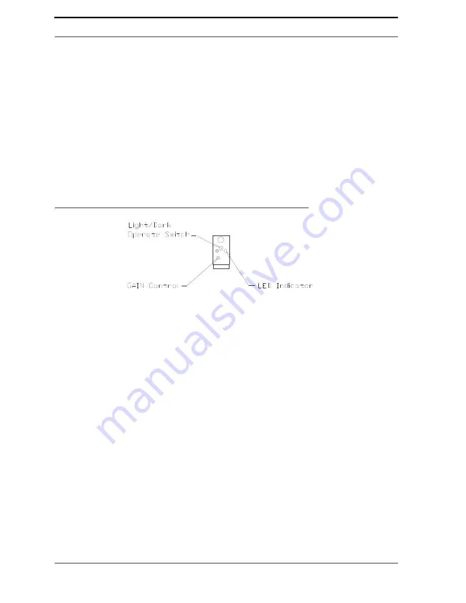
FIGURE 6-6.
PET sensor side view (cover removed)
1.
Enter Service Mode on the machine, and open the Diagnostic Program.
2.
Click on the Ultra-48 tab, and change the “Show:” drop box to “Sensors.”
3.
Find the
PET
sensor in the list.
4.
Remove the
PET
sensor back cover, revealing the
PET
sensor adjustment screws.
5.
Set the sensor for dark operation (
DO
) by turning the adjustment screw fully
counterclockwise.
6.
Turn the
GAIN
adjustment screw fully clockwise (15 turns).
7.
With the
PET
sensor not blocked, verify that the Diagnostic Program reports that
the
PET
sensor state is
OFF
.
8.
Insert a green
PET
bottle in the sensor beam. Verify that the
PET
sensor state is
ON
.
9.
Replace
PET
sensor back cover.
10.
Exit the Diagnostic Program.
6.5.4.3. Proximity Sensors
There are proximity sensors on the compactor and the Sorting Cylinder. On the compactor,
the proximity sensor monitors the rotations per minute of the main gear. If the speed drops too
low, the
RVM
Controller reports a stall. The proximity sensor on the Sorting Cylinder monitors
Summary of Contents for U48DFF
Page 1: ...ULTRA Series Service Manual May 6 2014...
Page 2: ......
Page 18: ...Chapter 2 Specifications 2 2 FIGURE 2 2 ULTRA 48 Configuration...
Page 40: ...Chapter 3 Hardware Components 3 18 FIGURE 3 17 MC1 Board Layout FIGURE 3 18 MC5 Board Layout...
Page 41: ...3 19 RVM Controller Box FIGURE 3 19 MD5 Board Layout...
Page 52: ...Chapter 4 RVM Software 4 6 FIGURE 4 6 Service Mode Time Out Screen...
Page 68: ...Chapter 4 RVM Software 4 22 FIGURE 4 18 Software Processes Overview...
Page 69: ...4 23 Software Theory of Operation FIGURE 4 19 Circuit Board Locations...


