Chapter 4
RVM Software
4-2
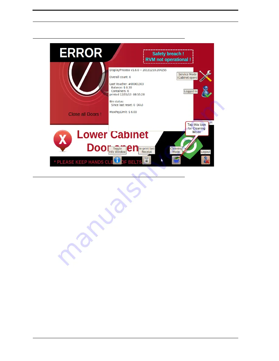
FIGURE 4-1.
Shop Mode
4.3. Service Mode
Service Mode allows technicians to perform in-depth diagnostics and maintenance tasks on the
RVM
.
To access this mode, the technician must have a pre-programmed
USB
drive (known as the Jump Drive)
and a corresponding
PIN
.
Service Mode comprises these programs:
•
Technician Interface - gives quick access to the most common tasks.
•
Diagnostic Program - gives access to Actuators, Sensors, and Thresholds.
•
Configuration editor - allows advanced users to edit the
RVM
’s configuration files.
4.3.1. Starting Service Mode
To enter Service Mode, follow these steps:
1.
Open the top cabinet door.
2.
Insert your Jump Drive into the
USB
port on the
RVM
Controller Box. A login
screen pops up.
3.
Use the on-screen keypad to enter your
PIN
.
4.
Next, the Technician Interface starts up, as shown in Figure 4-2.
Summary of Contents for U48DFF
Page 1: ...ULTRA Series Service Manual May 6 2014...
Page 2: ......
Page 18: ...Chapter 2 Specifications 2 2 FIGURE 2 2 ULTRA 48 Configuration...
Page 40: ...Chapter 3 Hardware Components 3 18 FIGURE 3 17 MC1 Board Layout FIGURE 3 18 MC5 Board Layout...
Page 41: ...3 19 RVM Controller Box FIGURE 3 19 MD5 Board Layout...
Page 52: ...Chapter 4 RVM Software 4 6 FIGURE 4 6 Service Mode Time Out Screen...
Page 68: ...Chapter 4 RVM Software 4 22 FIGURE 4 18 Software Processes Overview...
Page 69: ...4 23 Software Theory of Operation FIGURE 4 19 Circuit Board Locations...


